
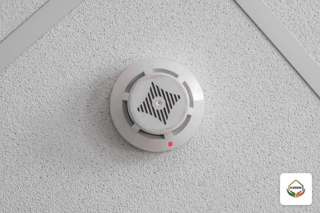
A smoke detector red light is the status LED in the detector head, and what it means depends on the device: is it connected to a conventional or addressable fire alarm panel, or is it a standalone battery smoke alarm? On many panel-connected detectors, a short periodic blink shows the detector is in normal operation, while a steady red light shows it has signalled an alarm to the panel. This article explains how to read the LED on Context Plus detectors used in fire alarm systems, based on the manufacturer’s datasheets, and when a remote indicator is needed above a room door or below a false ceiling.
Key takeaways
- LED behaviour is set by the manufacturer and varies by model, so the datasheet of the installed detector is the first reference.
- On Context Plus Series 65E conventional detectors the LED flashes in standby, lights red in alarm and goes off in a fault condition.
- On Context UL-PLUS addressable detectors the flashing LED is listed as an option, so a detector that does not blink is not necessarily faulty; the panel messages decide.
- A yellow LED on an isolating base is not an alarm: it means the base has isolated part of the loop because of a short circuit.
- A remote indicator is fitted where responders cannot see the detector LED, such as detectors in ceiling voids, locked rooms or air ducts.
In this article
- What does a smoke detector red light mean?
- How to read the detector LED by condition
- Context Plus conventional detectors: what the datasheet says about the LED
- Addressable detectors: what the datasheet says about the LED
- Steady red light on the detector and no smoke: what to do
- Standalone battery smoke alarms: why the light behaves differently
- Fire alarm remote LED indicator: when is it fitted above closed rooms?
- What to check at installation and handover
- Frequently asked questions
- Conclusion
What does a smoke detector red light mean?
The LED lets a technician see the state of a detector without opening it. The first question before reading it is whether the detector is part of a panel-based fire alarm system or a standalone battery alarm. In a panel-based system the detector normally does not sound by itself. It sends a signal to the panel, and the panel operates the sounders and shows the zone or address. Reading the detector LED is therefore always paired with reading the panel display or its zone indicators.
Panel-connected detectors show three basic states: a short repeated blink, a steady red light, or no light. The meaning differs slightly between manufacturers; the table below gives the common reading.
How to read the detector LED by condition
| What you see | Common meaning on a panel-connected detector | What to do |
|---|---|---|
| Short red blink every few seconds | Detector in standby, on models that blink in standby | Nothing, as long as the panel is normal with no faults |
| Steady red light | Detector in alarm and the signal has reached the panel | Check the panel and the area at once; do not reset until you are sure there is no fire |
| LED always off | Model without standby blink or with the blink option not enabled, a fault or loss of supply | Check the datasheet, then the panel messages; call maintenance if a fault is shown |
| Yellow LED on the base | On isolating bases, a short circuit with part of the loop isolated | A wiring fault for a technician, not a fire alarm |
Context Plus conventional detectors: what the datasheet says about the LED
In a conventional system each detector is wired to a zone on the panel, and each zone holds several detectors. When a detector goes into alarm it draws a higher current on the circuit, the panel shows an alarm for the whole zone, and the red LED of the detector that operated tells the technician which device triggered it.
The Context Plus conventional equipment catalogue states that Series 65E detectors (optical 55000-316IMC, ionisation 55000-216IMC) each have an LED that flashes in standby and lights red in alarm, and that the status indicator is off in a fault condition. Remote indicator connection is provided as standard through the -R terminal.
For the UL listed Series 65A detectors (optical 55000-326IMC, ionisation 55000-226IMC), the catalogue lists a flashing LED feature and a red LED alarm indication. The remote output R- is a current sink to the negative line limited to 17 mA, and the catalogue notes that a current-limiting series resistor may be required when a remote indicator is used.
On the panel side, the Context Plus conventional system submittal states that FP panels have latching fire outputs and non-latching fault outputs, separate indicators for open circuit, short circuit, sounder and battery or power supply faults, and an optional head removal monitoring facility. So the fire signal from the panel holds until reset, while the fault signal clears by itself once the cause is removed.
Addressable detectors: what the datasheet says about the LED
In an addressable system every device has its own address on the loop, and the panel polls the devices one by one and shows the address of the device in alarm. As an example of LED behaviour on a Context Plus addressable device, the datasheet of the 56000-005IMC manual pull station states that its red status LED flashes in normal operation and latches steady in alarm, and that flashing when polled is controlled by the panel. That statement covers the pull station; the Context Plus documents published on the AZEIDK site do not give the same detail for detectors.
For Context UL-PLUS addressable detectors, the datasheet lists a flashing LED among the range features, and the AZEIDK page for the 58000-650IMC optical detector describes 360° alarm indication with a flashing LED option. Standby blinking is therefore not fixed behaviour on every model, and an addressable detector that does not blink is not necessarily faulty. Check the datasheet and the fault display before replacing anything.
A frequent source of confusion on site is the isolating base. The datasheet for the Context Plus XPERT isolating base (45681-284IMC) states that its yellow LED is lit continually in the isolation condition, that is when a short circuit occurs on the loop, that the detector fitted to the base remains active, and that power is restored automatically to the isolated section once the fault is cleared. A yellow LED is a wiring fault message, covered in our article on fire alarm panel faults and fault messages.
Steady red light on the detector and no smoke: what to do
A steady red light means the detector has signalled an alarm, even if no smoke is visible now. The correct steps, in order:
- Read the panel display: which zone or address is in alarm, and since when.
- Physically check the area, including the ceiling void and any locked rooms, before treating the alarm as false.
- Do not remove the detector head to switch off the LED. The alarm is cleared by resetting the panel, not by removing the head, and on panels such as Context Plus FP the optional head removal monitoring adds a fault.
- Once safe, an authorised person resets the panel. If the same detector alarms again, suspect dust, steam, airflow or a detector type that does not suit the location.
- Record the event in the system log and request an inspection of the detector if it repeats.
How the detector is then tested is explained in how to test smoke detectors. Where the building has a fire and alarm maintenance contract, this kind of call falls under corrective maintenance and technical support.
Standalone battery smoke alarms: why the light behaves differently
A standalone smoke alarm combines the sensor, sounder and battery in one unit and does not report to a panel. Its LED and sound are all it has to show its condition, and their behaviour is defined by the manufacturer in the user manual. As an example from the products AZEIDK lists, the page for the FG SD-425 standalone detector describes a red LED for alarm status that flashes together with the audible alarm when smoke is detected.
For a comparison of the two, and when a standalone alarm is enough versus a full system, see standalone battery smoke alarm or fire alarm system.
Fire alarm remote LED indicator: when is it fitted above closed rooms?
A remote indicator is a red LED fitted where responders can see it and wired to the remote indicator terminal of the detector or its base, so it lights when the detector goes into alarm. It saves the technician from opening every door or lifting ceiling tiles to find which detector operated.
According to IAEI Magazine (May/June 2021) on the 2019 edition of NFPA 72, Section 17.4.6 requires detectors installed in concealed locations more than 3 m (10 ft) above the finished floor, or where the detector’s indicator is not visible to responding personnel, to have a remote alarm or supervisory indication in a location acceptable to the authority having jurisdiction. NFPA 72 is a technical reference adopted by the designer and consultant; what each project needs is settled in the approved design and with Civil Defense. Typical cases on site:
- Detectors above false ceilings or below raised floors in server rooms.
- Rooms that are locked most of the time: electrical rooms, stores, hotel or residential rooms locked from inside.
- Duct smoke detectors, covered in our article on duct smoke detectors.
- Any detector whose LED cannot be seen from the corridor because of height or mounting position.
The BF318 remote indicator with Context Plus detectors
The Context Plus catalogue lists the BF318 remote LED indicator with its conventional detectors, and the submittal for the addressable system describes it as an indicator with a high-intensity, wide-angle red LED, intended mainly to show the activation of hidden or out-of-sight detectors. The front label has a white write-on panel for the installer to add the detector location, and the unit fits 16 mm deep flush or surface back boxes. The submittal notes that detector head outputs are already current limited, so the indicator should be connected directly through its 0V and “LED only” terminals, after checking the detector manufacturer’s instructions.
For XPERT addressable detectors, the datasheet shows that the 45681-210IMC mounting base has +R and -R remote LED terminals, and gives the 55000-685IMC optical detector an internal 2.2 kΩ resistance on each remote terminal and a maximum remote LED current of 5 mA. These values apply only to these models; any other model is wired to its own datasheet.
What to check at installation and handover
- A schedule of detectors that need a remote indicator, with each indicator location shown on the drawings.
- The room number or detector location written on the indicator itself, so responders know where to go.
- Each remote indicator tested together with its detector, confirming it lights on the same alarm.
- The datasheet of every installed model handed over, with the meaning of the red and yellow LEDs explained to the building’s responsible person.
These items are part of fire alarm supply and installation, and available models can be reviewed under addressable fire alarm products. After handover, a preventive maintenance contract covers fire, safety and alarm systems together.
Frequently asked questions
Why is there a flashing red light on my smoke detector?
On many panel-connected detectors a short periodic blink indicates normal operation, as on Context Plus Series 65E detectors. No action is needed while the panel shows no alarm or fault.
What does a steady red light on a smoke detector mean?
It usually means the detector is in alarm and has signalled the panel. Check the area and the panel display before resetting.
My smoke detector never blinks. Is it faulty?
Not necessarily. Some models do not blink in standby, and on others the blink is an option. Check the datasheet and panel messages; on Context Plus Series 65E detectors the LED goes off in a fault condition.
How do I turn off the red light on a smoke detector?
The light usually stays on until the panel is reset after confirming there is no fire. Removing the detector head does not solve it and may show as a fault on the panel.
What is a fire alarm remote LED indicator for?
It shows outside a room or below a ceiling that a hidden detector is in alarm, so the technician reaches the right device without opening every room.
What does a yellow LED on a detector base mean?
On isolating bases such as the XPERT 45681-284IMC it means the base has isolated part of the loop because of a short circuit. It is a wiring fault, not a fire alarm.
Conclusion
A smoke detector red light is read together with the panel, not on its own: a periodic blink is usually normal operation, a steady light is an alarm, and an LED that stays off calls for a check of the datasheet and panel messages. For hidden detectors, a remote indicator solves the visibility problem, provided it is planned in the design, labelled with the detector location and tested at handover.
Detectors stuck on red, or rooms that need remote indicators? Send us the panel type, photos of the detectors and the drawings, and our team will review the situation and propose a solution. Contact the AZEIDK team
Related guides
- Fire Alarm Maintenance Checklist for Saudi Facilities: Fire Alarm, Sprinklers, Fire Pumps and Extinguishers (NFPA 72, 25 and 10)
- Archive Room Fire Protection: Sprinklers or Clean Agent for Records
- Mini CCTV Cameras: Small Cube and Pan-Tilt Cameras from EZVIZ and Hikvision, Wi-Fi or SD Card, and What Saudi Law Allows
- Safety Signs in Saudi Arabia: Assembly Point, Emergency Exit, No Smoking and CCTV Surveillance Signs