
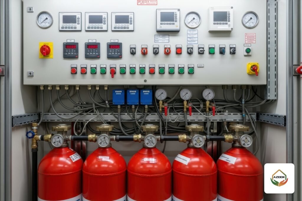
An FM200 testing procedure before handover proves that every step of the sequence of operation works as designed, from the first detector to the release command, without discharging the agent. It covers a review of cylinders, piping and nozzles, an enclosure integrity test, and a full functional test of both alarm stages, the time delay, the abort switch, manual release, HVAC shutdown and damper closure, and the signals sent to the building fire alarm panel. This article walks through those steps in the order they happen on site, as part of AZEIDK special fire suppression systems.
Key takeaways
- FM-200 is the common trade name for HFC-227ea. The technical reference for design and testing is NFPA 2001, and the edition applied on each project is set by the Saudi code and Civil Defense.
- Acceptance testing is functional. It does not normally need an agent discharge, provided the cylinder actuators (solenoids) are disconnected first.
- The sequence of operation is tested step by step against the approved cause and effect matrix.
- The abort switch works only while it is held, and manual release overrides it.
- All test results go to the owner, who keeps them for the life of the system.
In this article
- What does FM-200 testing and commissioning before handover involve?
- What is the FM200 sequence of operation?
- How do the abort switch and manual release work, and how are they tested?
- FM200 testing procedure: what are the stages before handover?
- How are the alarm and ventilation interfaces tested?
- What documents are handed over after testing?
- What are the common mistakes in FM-200 testing and commissioning?
- Frequently asked questions
- Conclusion
What does FM-200 testing and commissioning before handover involve?
After installation, the system goes through testing and commissioning before the owner accepts it and before the Civil Defense approval request. The goal is to prove that the installed system matches the approved drawings and that detection, alarm, control and release work in the correct sequence.
The technical reference for clean agent systems is NFPA 2001, currently the 2025 edition. The edition that applies to each project is set by the Saudi Fire Protection Code (SBC 801) and Civil Defense requirements, so it must be stated in the design basis. Clause-level detail is in our NFPA 2001 guide. This article focuses on site practice.
NFPA 2001 (2018 edition) requires the completed system to be reviewed and tested by people with knowledge and experience of this type of system, the installation to be checked against the manufacturer’s instructions, and the actual hazard dimensions to be checked against the drawings. Where the project specification calls for integrated testing of fire protection and life safety systems, it is done to NFPA 4.
A full agent discharge is not normally part of acceptance. Engineering references note that pipe pressure tests, nitrogen puff tests and door fan tests have replaced it, unless the authority having jurisdiction asks for one.
What is the FM200 sequence of operation?
The designer defines the sequence in the cause and effect matrix, and the releasing panel technician programs it. The common sequence on projects uses cross-zoned detection, which means release starts only after two detectors on two different circuits confirm the fire:
| Step | What normally happens | How to test it without discharge |
|---|---|---|
| First detector operates | First-stage alarm in the room and an alarm signal to the building panel | Operate the detector with a test tool and confirm the signal on both panels |
| Second detector operates | Second-stage (pre-discharge) alarm and start of the time delay | Operate a detector on the second circuit and time the delay with a stopwatch |
| During the time delay | HVAC shutdown, damper closure and warning signs at the door, as designed | Watch fans stop and dampers close, and record the actual times |
| End of time delay | Release command to the cylinder actuator | Measure the output voltage or use a simulator in place of the disconnected actuator |
| Agent flow | Discharge pressure switch triggers the “agent discharged” alarm | Operate the switch by hand and confirm the signal and the lamp outside the room |
The time delay is set in the design and is often around 30 seconds to allow evacuation. What matters in the test is that the measured time matches the approved matrix. For more on the matrix, see fire alarm cause and effect matrix. For hold and abort buttons on an actual releasing panel, see gas suppression release sequence and the EP203 panel.
How do the abort switch and manual release work, and how are they tested?
The abort switch is a control used during the countdown to hold the release or extend the delay. NFPA 2001 (2018 edition) requires its operable part to be mounted between 1.07 m and 1.22 m above the floor. Records of completion based on NFPA 2001, such as the Boston Fire Department form, check that the switch is a deadman type that works only while someone keeps pressing it, that it is clearly labeled, and that the manual release station overrides it.
What happens when the switch is released depends on how the releasing panel is programmed and the options its manufacturer allows. Some modes resume the countdown where it stopped and others restart it. The behavior must be written in the matrix, approved by the consultant and tested exactly as written.
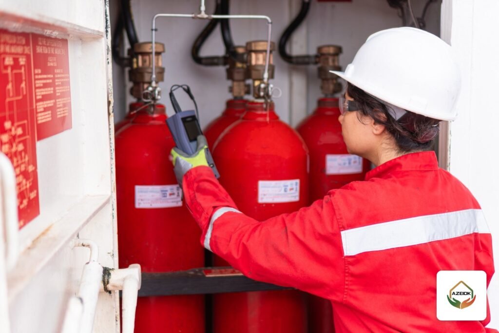
Manual release has two levels: an electrical pull station outside the room that releases through the panel, and a manual button on the cylinder actuator itself. The datasheet for the American Fire Control FM-200 system, for example, warns that manual actuation at the cylinder is for emergencies only, as a last resort. During testing the pull station is operated with the actuator disconnected, and every function is checked against the design.
FM200 testing procedure: what are the stages before handover?
The order below follows the items on clean agent records of completion based on NFPA 2001 and the manufacturer’s instructions. Final details come from the installation manual of the supplied system and the project specification.
1. Mechanical review
- Room dimensions, piping, nozzles and pipe sizes match the drawings, and nozzles are oriented correctly.
- Cylinders and brackets are secured in place, and the weight or pressure of each cylinder is recorded.
- The agent quantity supplied suits the actual room volume.
- Piping is pneumatically tested and a nitrogen puff test confirms the nozzles are clear. The Boston Fire Department record of completion, for example, states 40 psig for 10 minutes with no more than 8 psig loss.
2. Enclosure integrity test
A door fan test calculates how long the room holds the concentration. It is covered in detail in clean agent room integrity test, and openings and penetrations must be sealed before it.
3. Electrical review
- Wiring matches the drawings, with no short circuits or ground faults on field circuits.
- The releasing panel is on a dedicated, labeled circuit, with standby batteries of the required capacity.
- Detectors are of the type and in the locations shown on the drawings, away from air outlets that would affect their response.
4. Preliminary functional test
- Notify the monitoring station and building management before starting.
- Disconnect the cylinder actuators. On the AFC-227 system, for example, a dedicated supervisor switch monitors the electric actuator position, so removing it raises a supervisory signal on the panel, which is a useful check in itself.
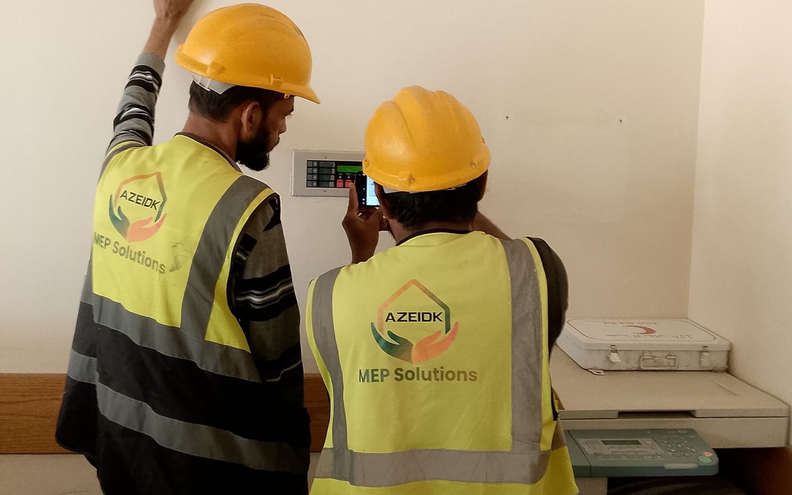
- Test every detector, and open every supervised circuit to confirm a trouble signal on the panel.
5. Full functional test
- Operate the first and second stages and check every output and the time delay.
- Test manual release and the abort switch as described above.
- Test automatic valves as far as possible without releasing agent.
- Confirm alarm, supervisory and trouble signals reach the building panel or monitoring station, and test primary power failure per the manufacturer’s instructions.
6. Return to normal
Reinstall the actuators and confirm the supervisory signal clears, reset any pressure switch that needs manual reset, and record the final panel status.
How are the alarm and ventilation interfaces tested?
Interface failures are a leading cause of poor real-world performance. If an air handling unit keeps running during discharge, or a damper stays open, the agent leaks and the concentration drops before the hold time ends. That is why NFPA 2001 (2018 edition) requires fan coastdown and damper closure times to be verified where they are part of system operation.
The same edition requires the releasing panel to be monitored by the building fire alarm system for alarm, supervisory and trouble signals. In practice this means interface modules between the two panels, and each signal is tested on its own. Where a discharge pressure switch is fitted, it sends the “agent discharged” signal. On the AFC-227 system, for example, the compact switch is factory set at 25 psi.
Programming these signals on the building panel is a separate step, covered in fire alarm panel programming.
What documents are handed over after testing?
- Signed test reports for each stage. NFPA 2001 requires them to be given to the owner and kept for the life of the system.
- The enclosure integrity test report.
- The final cause and effect matrix as tested.
- As-built drawings, the O&M manual and datasheets.
- A record of cylinder weights or pressures at handover, as a reference for maintenance.
These documents form the basis of the Civil Defense approval file and are compiled under documentation and final handover.
What are the common mistakes in FM-200 testing and commissioning?
- Starting functional tests before disconnecting the actuators. This is the most dangerous mistake, because it can end in a real discharge.
- Testing the time delay without timing it or comparing it with the matrix.
- Not testing what the abort switch does after it is released.
- Running the room integrity test before ceiling work and penetrations are finished, so it has to be repeated.
- Forgetting to reinstall actuators after testing, or ignoring the supervisory signal on the panel.
- Changing the room use or size after design without rechecking the agent quantity.
Frequently asked questions
Does FM-200 acceptance testing require discharging the agent?
Not normally. Acceptance relies on functional testing with actuators disconnected, pipe testing, a nitrogen puff test and an enclosure integrity test, unless the authority having jurisdiction asks otherwise.
What is the FM200 sequence of operation in short?
A first detector gives a first-stage alarm. A second detector starts the pre-discharge alarm, the time delay and HVAC shutdown. Then the release command goes out, and the pressure switch confirms discharge.
How long is the time delay before FM-200 release?
It is set in the design and is often around 30 seconds. The test confirms that the actual time matches the approved matrix.
Does the abort switch cancel the system?
No. It holds or extends the countdown only while pressed, and manual release overrides it. What happens after release depends on the panel programming.
Who carries out FM200 testing and commissioning?
A team with knowledge and experience of the system, usually the installing contractor or the supplier’s agent, witnessed by the consultant and following the manufacturer’s manual.
What is the difference between commissioning and a room integrity test?
Commissioning checks detection, control, release and interfaces. The room integrity test measures how well the room holds the agent concentration. Both are needed before handover.
Conclusion
An FM-200 system’s performance on the day of a fire is decided on the day of testing. Disconnect the actuators first, test the full sequence against the approved matrix, confirm how the abort switch and manual release behave, check that HVAC stops and dampers close, then return the system to normal and hand every report to the owner.
Getting ready to accept a gas suppression system? The AZEIDK team supports supply, installation, testing, commissioning and handover, and the approval file. Talk to the AZEIDK team
Related guides
- SLA in a Fire System Maintenance Contract: Response Times, Planned Visits and Penalties
- American Fire Control (AFC) in Saudi Arabia: Valves & Suppression
- Fire Valve Price in Saudi Arabia: What Drives the Cost (OS&Y vs Butterfly, Flanged vs Grooved, Size, UL/FM)
- Factory and Industrial Fire Protection: Engineering Guide