
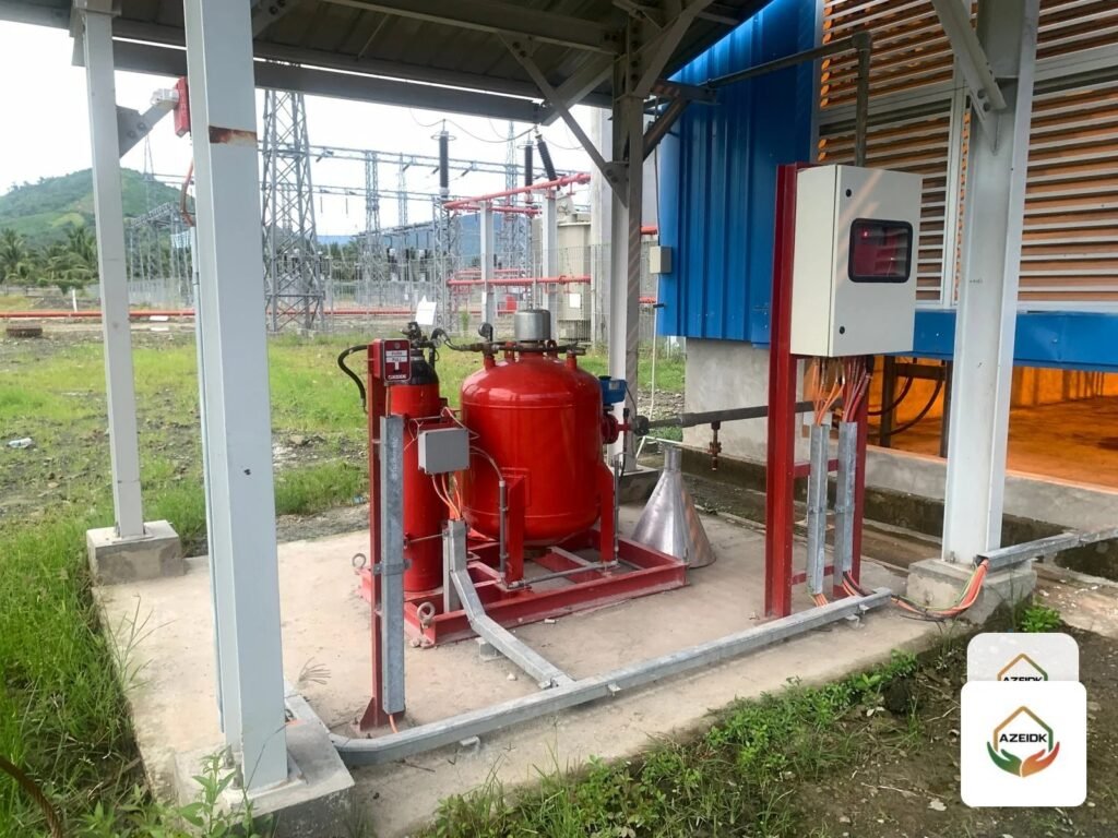
FM200 system components form one mechanical chain: a pressurised cylinder holding the agent, a device that opens its valve, hoses, a manifold and check valves that carry the gas, pressure switches and indicators that supervise it, and nozzles that distribute it in the room. In the Context Plus 227 (HFC-227ea) range, each link in that chain has a specific model with a job no other part can do.
This guide maps the components from cylinder to nozzle as AZEIDK supplies them under its special fire suppression systems, explains single-cylinder, multi-cylinder and main/reserve arrangements, and lists what to check on each spare part before ordering.
Key takeaways
- FM-200 is a trademark of The Chemours Company. The agent itself is HFC-227ea, sold by Context Plus as Context Plus 227.
- Context Plus cylinders come in nominal capacities from 35 to 1,200 lb, super-pressurised to 360 psi or 500 psi according to the product page.
- The master cylinder opens electrically by solenoid or manually; slave cylinders open pneumatically through the CP61041 piston actuator.
- A main/reserve system needs the CP60911 selector switch and shuttle check valves so the reserve charge cannot flow back into the empty main cylinder.
- The CP50339 switch confirms discharge, the CP50138-1 switch signals low cylinder pressure, and the CP60020 indicator measures liquid level.
In this article
- What are the components of an FM200 system, from cylinder to nozzle?
- Context Plus 227: how does it relate to FM-200?
- FM200 cylinders: capacities, pressure and valves
- How is the cylinder opened? Solenoids, piston actuator and manual head
- Single cylinder or multi-cylinder system?
- Main and reserve cylinder banks
- Pressure switches and level indicators: how is the system supervised?
- Discharge nozzles: size and distribution pattern
- What should the component submittal include?
- Common mistakes when ordering FM200 system components and spares
- Frequently asked questions
- Conclusion
What are the components of an FM200 system, from cylinder to nozzle?
The table lists the mechanical components of a Context Plus 227 system as shown on AZEIDK’s Saudi product pages, in the order the gas travels.
| Component | Model / sizes | Role in the system |
|---|---|---|
| Extinguishing agent | Context Plus 227 (HFC-227ea) | Clean agent stored as a liquid, discharged as a vapour |
| Storage cylinder and valve | 35 to 1,200 lb; 1″, 1-1/2″, 2-1/2″ and 4″ valves | Stores the agent under pressure and opens the discharge path |
| Electric release solenoid | CP50025-2 and CP50025-6 | Opens the cylinder valve on a 24V DC signal from the release panel |
| Latching solenoid | CP50026 | Electrical release, with provision for a manual control head on top |
| Piston actuator and manual control head | CP61041 and CP61033 | Pneumatic opening of slave cylinders; manual release at the cylinder |
| Actuation hoses and fittings | 1/4″ in 12″, 20″, 24″ and 36″ lengths | Carry actuation pressure from master to slave cylinders |
| Cylinder discharge flex hoses | 1″, 1-1/2″, 2-1/2″ and 4″ | Connect the cylinder to the pipework or manifold |
| Manifold check valves and shuttle valves | 1″, 1-1/2″, 2-1/2″ and 4″ (manifold); 1″ and 1-1/2″ (shuttle) | Prevent back-flow and agent loss in multi-cylinder systems |
| Main/reserve selector switch | CP60911 | Transfers release from the main bank to the reserve bank |
| Pressure switches | CP50339 and CP50138-1 | Discharge confirmation and cylinder pressure supervision |
| Liquid level indicator | CP60020 series | Measures agent quantity during inspection |
| Discharge nozzles | 1/2″ to 2″, 180° or 360° | Distribute the agent in the room, ceiling void and raised floor |
Context Plus 227: how does it relate to FM-200?
The market uses “FM-200” for HFC-227ea (heptafluoropropane), but FM-200 is a Chemours trademark. Context Plus 227 is Context Plus’s trade name for the same agent. Its product page states it is UL listed (GARZ2.EX16152) and FM approved, and complies with ASTM D6064 and NFPA 2001.
The agent is stored as a liquefied compressed gas and discharged as a colourless, electrically non-conductive vapour that leaves no residue. The datasheet gives a minimum purity of 99.95%, moisture below 10 ppm and acidity below 1 ppm as HF. Design concentration, agent quantity and occupant safety are covered in our article on the FM-200 fire suppression system, so they are not repeated here.
FM200 cylinders: capacities, pressure and valves
Context Plus clean agent cylinders are stored-pressure units for total flooding of Class A, B and C hazards in an enclosure. Each is supplied with its valve and the top plug adapter that the actuators mount on. The product page lists:
- Nominal capacities of 35, 70, 150, 250, 375, 560 and 1,200 lb.
- Super-pressurisation to 360 psi (24 bar) or 500 psi (34 bar).
- Stainless-steel valves in 1″, 1-1/2″, 2-1/2″ and 4″ sizes, depending on capacity.
- An operating temperature range of 0°C to 54°C.
- UL listing.
Systems are designed and installed to the Context Plus design, installation, operation and maintenance manual using the manufacturer’s flow calculation software. Cylinder size therefore comes from the calculation, which also sets pipe and nozzle sizes, not from room volume alone.
How is the cylinder opened? Solenoids, piston actuator and manual head
The cylinder valve is normally closed. Every Context Plus release device works the same way: it vents the pressure above the valve piston, the piston slides upward and discharge begins.
| Device | Operation | Notes from the product page |
|---|---|---|
| CP50025-2 / CP50025-6 solenoid | Electric, 24V DC | CP50025-2 suits 35 to 560 lb cylinders and not the 1,200 lb cylinder; CP50025-6 is designed for the 1,200 lb cylinder. It must connect to a Context Plus approved extinguishing panel, with the circuit supervised for open circuit, short circuit and earth fault |
| CP50026 latching solenoid | Held latched without power until the release signal | Opens the Schrader valve on the top plug adapter; designed for use with the CP61033-2 local manual control head |
| CP61041 piston actuator | Pneumatic, using pressure from the master cylinder’s “M” port | Opens several slave cylinders from one master through 1/4″ copper tube or metal flex hose |
| CP61033 local manual control head | Lever-driven push rod | Solid brass, self-venting, with a safety pull-pin against accidental discharge |
What happens before the signal reaches the solenoid (cross-zoned detection, pre-discharge delay, hold and abort buttons) belongs to the control panel and is covered in our article on the gas suppression release sequence and the EP203 panel.
Single cylinder or multi-cylinder system?
When the calculation needs only one cylinder, the solenoid mounts directly on it and a discharge hose feeds the pipework. When it needs more, three things change:
- Actuation: the solenoid goes on the master cylinder only, and a CP61041 piston actuator goes on each slave. Actuation pressure travels through 1/4″ hoses and flare fittings with 7/16-20 UNF ends, plus flare elbows, tees, nipples and caps.
- Manifolding: cylinders connect to a common discharge manifold through cylinder discharge flex hoses: 1″, 1-1/2″ and 2-1/2″ × 18″ with male NPT ends, or 4″ × 30-1/2″ stainless-steel braided with Victaulic ends.
- Back-flow protection: a check valve sits between each cylinder and the manifold. The manifold and shuttle check valves page states that it prevents agent loss if a cylinder is disconnected at the time of discharge, and back-flow into the other cylinders.
Main and reserve cylinder banks
Some facilities want a reserve bank that protects the room immediately after the main bank discharges, without waiting for a recharge. This adds two components:
- Shuttle check valve: brass, with 1″ or 1-1/2″ NPT threads. It connects the main and reserve cylinders to the same pipework and nozzles, and stops the reserve charge flowing back into the empty main cylinder.
- CP60911 selector switch: transfers the electrical release supply from main to reserve. It has two independent dry contacts (common/N.C. and common/N.O.) and comes with a back box.
The datasheet sets the order after a discharge: reset the field devices, return the extinguishing panel to normal protection mode, and only when every device is in standby move the switch to “Reserve”. The empty main cylinder can then be removed for recharge. In other words, transfer follows the reset, never the other way round.
Pressure switches and level indicators: how is the system supervised?
AZEIDK supplies the CP50339 and CP50138-1 pressure switches, and they do different jobs:
- CP50339 discharge pressure switch: fitted anywhere on the discharge piping between cylinder and nozzle. It provides form C contacts rated 15A at 125/250V AC for alarm and auxiliary functions, and has an external manual reset button that must be pressed after system actuation.
- CP50138-1 cylinder supervisory switch: operates if cylinder pressure falls below 291 ±10 psig, for example after a leak, and is wired into a supervised circuit to give a trouble signal at the panel. It is UL listed.
Agent quantity is checked with the CP60020 liquid level indicator, a manual device for vertically mounted cylinders whose reading is converted to weight using the chart in the Context Plus manual. The page gives accurate readings from about 4°C to 32°C, with models for 150/250 lb, 375/560 lb and 1,200 lb cylinders. Semiannual checks and acceptable loss limits are covered in our FM-200 system maintenance article.
Discharge nozzles: size and distribution pattern
Discharge nozzles are the last link and spread the agent in a set pattern and concentration. Sizes are 1/2″, 3/4″, 1″, 1-1/4″, 1-1/2″ and 2″, each in 180° and 360° patterns, with optional deflector plates to protect sensitive ceiling tiles. The product page states that discharge completes in 10 seconds or less when installed within the limits of the installation manual.
Nozzle size, number and location come from the flow calculation. Do not swap a nozzle for a different size or pattern on site without recalculating.
What should the component submittal include?
For the consultant’s material approval, and later for the Civil Defense approval file, the submittal should cover every link in the table above, not just the cylinder and agent:
- A datasheet for each component, with the model number that will actually be supplied.
- Listing or approval status exactly as stated for each model: several components are described as UL listed, and the agent as UL listed and FM approved.
- Flow calculation output: agent quantity, pipe sizes, and each nozzle’s size and pattern.
- The wiring diagram between the solenoid and the release panel, naming the Context Plus approved panel used.
Common mistakes when ordering FM200 system components and spares
- Ordering a CP50025-2 solenoid for a 1,200 lb cylinder, which it does not suit; that cylinder needs the CP50025-6.
- Buying spares from another manufacturer’s system because “the gas is the same”. Both may hold HFC-227ea, but the valve, top plug adapter and release devices are specific to each manufacturer.
- Leaving out manifold check valves, which are what prevent agent loss if a cylinder is disconnected at the moment of discharge.
- Confusing the two pressure switches: CP50339 does not supervise cylinder pressure, and CP50138-1 does not confirm discharge.
- Overlooking the manual reset on the CP50339, although the product page requires it to be pressed after every actuation.
- Relying on the pressure gauge to judge agent quantity instead of reading the level indicator and converting it to weight with the manufacturer’s chart.
Frequently asked questions
What is the difference between FM-200 and Context Plus 227?
Both are trade names for HFC-227ea. FM-200 is a Chemours trademark; Context Plus 227 is the Context Plus name, and its page states it is UL listed and FM approved.
Does every cylinder need a solenoid?
No. In a multi-cylinder system the solenoid goes on the master cylinder, and slave cylinders open through CP61041 piston actuators driven from the master’s “M” port.
What does a shuttle valve do in an FM200 system?
It connects the main and reserve banks to the same pipework and stops the reserve agent flowing back into the empty main cylinder after discharge.
When does the CP50138-1 switch operate?
When cylinder pressure falls below 291 ±10 psig. It then sends a trouble signal to the release panel through a supervised circuit.
Can the system be released manually at the cylinder?
Yes, with the CP61033 local manual control head, which has a safety pull-pin. The CP61033-2 version fits on top of the CP50026 latching solenoid.
Conclusion
FM200 system components work as one chain, and a mismatched link stops the rest: a solenoid that does not suit the cylinder, a manifold without check valves, or a selector switch moved before the reset. Every link in the Context Plus 227 range has a defined model and a published datasheet, so matching the calculation, the submittal and the parts delivered to site is the starting point for both supply and maintenance.
Need spares or a bill of materials for a Context Plus 227 system? Send us the cylinder sizes and quantities and the current release method, and we will confirm the matching models and datasheets for each component. Contact the AZEIDK team