
FM200 installation (an HFC-227ea clean agent system) follows a fixed order: mount the cylinders on their brackets, run the piping and nozzles at the sizes produced by the system’s listed flow calculation software, install the releasing panel, manual release, abort switch and detectors, then carry out the room integrity test and functional tests before handover. Any site change from the calculation means recalculating.
Key takeaways
- Pipe sizes and nozzle orifices come from the listed calculation software for the system and are not changed on site without a new calculation.
- The Context Plus datasheet sets bracket count by cylinder size: one bracket from 35 to 250 lb, two brackets from 275 to 560 lb.
- The AFC-227 datasheet calls for vertical cylinder mounting and nozzles no more than 0.3 m below the ceiling.
- The releasing panel discharges according to the detection logic set in the design, which on many projects requires two detectors to confirm, with a manual release at the exit and an abort switch.
- A room integrity test under NFPA 2001 Annex C shows the room will hold the design concentration.
In this article
- Before FM200 installation: what must be approved?
- Stage one: mounting the FM200 cylinders
- Stage two: piping and nozzles
- Stage three: releasing panel, manual release and abort
- Coordinating with other trades in the room
- Stage four: room integrity test and pre-handover tests
- Common FM200 installation mistakes
- Frequently asked questions
- Conclusion
Before FM200 installation: what must be approved?
Installation does not start until three things are approved: the agent quantity calculation for the room, the hydraulic flow calculation from the system’s listed software, and the shop drawing showing cylinders, piping, nozzles, detectors and release stations. The room itself is reviewed with the consultant: openings, doors, air paths and air conditioning.
AZEIDK works with two available systems, Context Plus 227 and the American AFC FM-200 system, as part of its special fire suppression systems. Each is installed to its own manual and calculation software, and components from the two are never mixed.
Stage one: mounting the FM200 cylinders
The cylinder is the heaviest item in the system and holds agent under pressure. The Context Plus datasheet gives an operating pressure of 360 psi at 70°F and an operating temperature range of 0 to 54.4°C, so the location must be away from heat sources and direct sun.
| Item | Context Plus 227 | AFC-227 |
|---|---|---|
| Mounting | Brackets: one for 35 to 250 lb cylinders, two for 275 to 560 lb | Strap sets on channel struts fixed to a rigid wall or steel frame |
| Cylinder position | Per the manual | Vertical |
| Pressure supervision | Pressure switch signals when pressure drops to 291±10 psig | Gauge and switch set at 19.9±1.5 bar (277.1±21.8 psi) |
| Manual release at the cylinder | Local manual control head CP61033 with safety pin | Push button on the solenoid cutter, manual reset required |
Project specifications commonly require cylinders to be placed so they can be removed easily for service and refilling. See clean agent cylinders for available sizes.
Stage two: piping and nozzles
FM200 piping is shorter and smaller than a sprinkler network, but less forgiving. Agent must reach every nozzle in the calculated quantity and time, and extra length or fittings beyond the calculation change the result.
- Pipe: published clean agent project specifications call for Schedule 40 black or galvanized steel to ASTM A53 or A106. Pipe, fittings and pressure class are approved per project from the manual and calculation.
- Cleanliness: pipe is cleaned inside before erection and blown out before nozzles go on, because debris can block an orifice.
- Support: piping is firmly supported because discharge creates reaction forces. Some specifications require a support within 300 mm of each nozzle.
- Flexible hoses: between cylinder and manifold, with a bend radius not below the manufacturer’s minimum; the AFC-227 datasheet gives 350 mm for the 50A hose.
Discharge nozzles come in two types: 360-degree at the centre of the coverage area and 180-degree on the wall. The AFC-227 datasheet gives a protected room height of 0.3 to 4.5 m and a maximum of 0.3 m from the ceiling to the nozzle. Each orifice is drilled to the calculation, so two nozzles are never swapped.
Stage three: releasing panel, manual release and abort
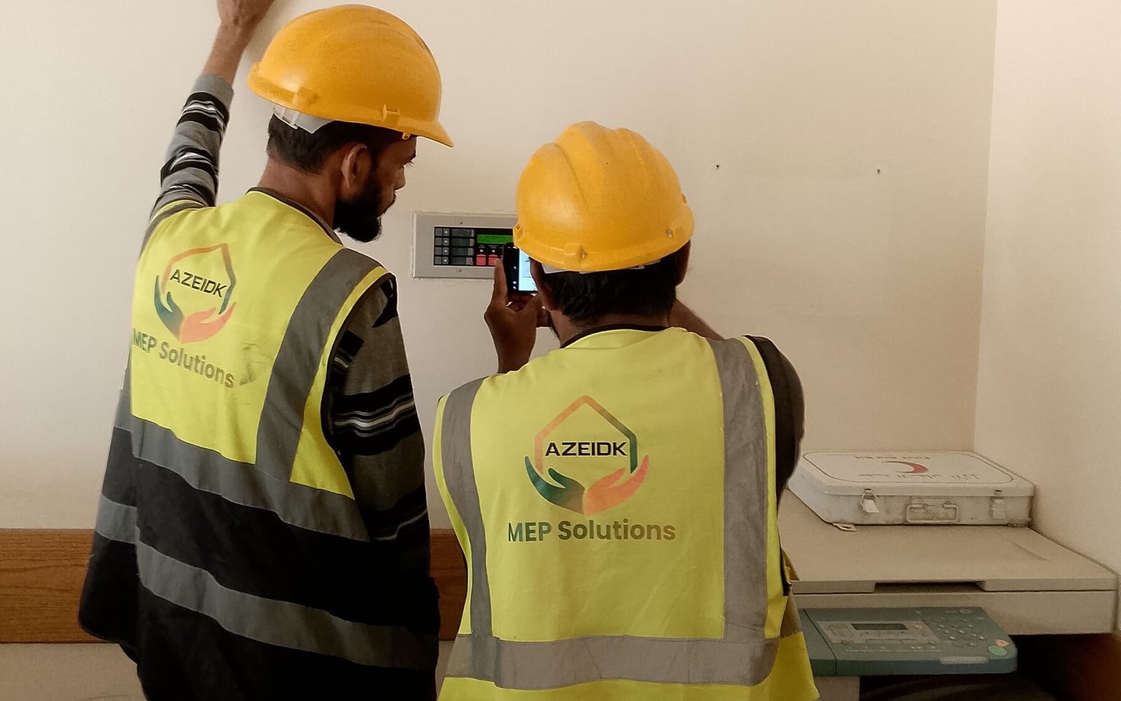
The releasing panel receives detector signals and runs the sequence: first alarm, second alarm and countdown, then discharge through the solenoid on the cylinder valve. Ventilation shutdown and closing of air paths are part of that sequence as designed.
- Manual release: at each exit from the room. See extinguishant release call points.
- Abort switch: next to the exit; some specifications require a dead-man (constant pressure) type.
- Solenoid: fitted to the cylinder valve last, after the panel is tested, to avoid accidental discharge.
- Warning signs: on the room doors, with the operating sequence posted next to the stations.
Check that the solenoid is compatible with and listed for the panel used. The AFC-227 datasheet, for example, names the Potter PFC-4110RC as a compatible panel for its solenoid cutter. The AZEIDK range also includes the Context Plus EP203 extinguisher control panel.
Coordinating with other trades in the room
An FM200 room is not the suppression team’s work alone. The room itself is part of the system, and every opening, door or air path affects how well it holds the agent. These items are followed up with the main contractor and other trades during installation:
- Walls and ceiling: seal cable and pipe penetrations, including those above the suspended ceiling and below the raised floor.
- Doors: self-closing doors and seals as the design requires.
- HVAC and ventilation: air paths closed on a signal from the releasing panel (by the HVAC trade), or shutdown of units that draw air from outside the room, as designed.
- Raised floor: where the design includes it, nozzles and detectors go in as the approved drawing shows.
- Power: a dedicated supply for the releasing panel and standby batteries sized by calculation.
Leaving these items to the end is the most common reason for a failed integrity test and a late handover.
Stage four: room integrity test and pre-handover tests
When installation is complete, the room is tested with a door fan under NFPA 2001 Annex C, as our room integrity test article explains. Functional tests follow as part of testing and commissioning:
- Compare the installation with the approved drawing: pipe lengths and sizes, nozzle locations and sizes.
- Static pressure test of the piping; if water is used, dry the pipe thoroughly afterwards.
- Confirm piping is blown clear, tight and supported.
- Test every detector and every releasing device in all operating modes, and measure the time delay.
- Operate the abort switch and confirm the trouble signal, and that manual release overrides the abort.
- Test ventilation shutdown, closing of air paths and automatic doors.
- Weigh the cylinders or verify agent quantity before returning the system to service.
These items appear in the AXA XL acceptance test guideline for special extinguishing systems. After handover, the system moves into periodic maintenance.
Common FM200 installation mistakes
- Adding an elbow or extending a pipe to clear a ceiling clash without recalculating.
- Swapping two nozzles after drilling, or fitting a nozzle from another system.
- Fitting the solenoid to the cylinder before the panel is tested.
- Wall openings above the suspended ceiling left open, so the integrity test fails.
- A cylinder placed where it is hard to remove or exposed to heat.
- No warning signs or operating sequence at the doors.
Frequently asked questions
What are the FM200 installation steps?
Mount the cylinders, run piping and nozzles to the calculation, install the panel, detectors and stations, then carry out the room integrity test, functional tests and handover.
Can an FM200 pipe route be changed on site?
Only after the hydraulic calculation is rerun and approved, because route length and fittings affect flow and discharge time.
When is the room integrity test done?
After all openings are sealed and the room is ready, before handover. Some specifications also ask for a preliminary test before installation.
Where does the abort switch go?
Next to the room exit with the manual release, with a sign explaining its use.
Is agent discharged during the acceptance test?
Not necessarily. A room integrity test and circuit and device tests without discharge are usually enough, unless the project calls for a discharge test.
Can FM200 be installed in a live, operating room?
In most cases yes, with drilling and pipe work scheduled so equipment keeps running, and openings sealed before the integrity test. The solenoid goes onto the cylinder last.
Conclusion
FM200 installation follows the calculation to the letter: cylinders on their brackets, clean pipe at the calculated sizes, nozzles in the right places, a tested panel and stations, and a tight room. The governing standard for this stage is covered in our NFPA 2001 guide.
Preparing a server or electrical room for FM200? Send the room layout and dimensions, and the AZEIDK installation team will handle calculation, installation and testing. Talk to the AZEIDK team
Related guides
- Turnstile Gates: Tripod, Flap, Swing or Full Height for Offices, Gyms and Factories
- Safety Signs in Saudi Arabia: Assembly Point, Emergency Exit, No Smoking and CCTV Surveillance Signs
- Renewing a Salamah Civil Defense Licence in Saudi Arabia: Licence Types, Renewal Steps and Pre-Inspection Systems
- Fire Extinguisher Refilling in Saudi Arabia: When It Is Needed, What Happens in the Workshop and How to Accept the Unit