

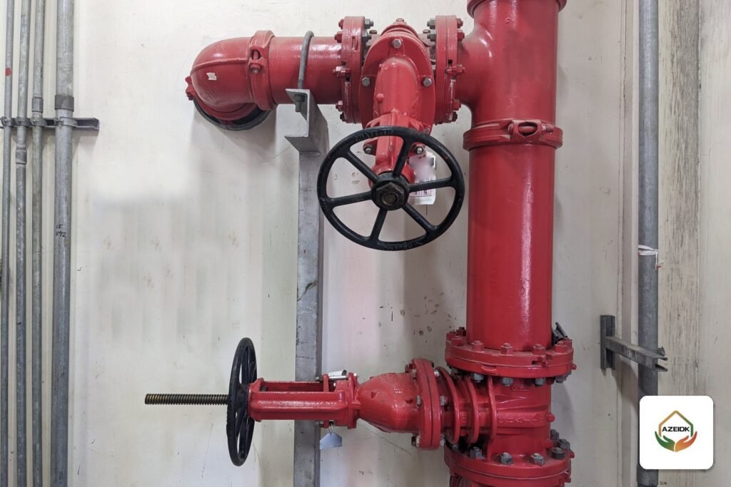
A fire pump calculation starts from the demand point in the approved hydraulic calculations: the highest flow the system needs and the pressure required at the pump discharge flange. Subtract the lowest available suction pressure to get the net pressure. Then choose a standard rated capacity whose curve covers that point, and check that the pump delivers 150% of rated flow at no less than 65% of rated pressure, with shutoff pressure no higher than 140%. The jockey pump is sized separately and only makes up leakage. This guide walks through each step with a worked example, for engineers, contractors and owners reviewing a quotation for the fire pumps AZEIDK supplies.
Key takeaways
- The design point comes from the approved hydraulic calculations, not from a rule of thumb based on building size.
- Net pump pressure = pressure required at discharge minus the lowest suction pressure available at the same flow.
- At 150% of rated flow the pump must still deliver at least 65% of rated pressure.
- Shutoff (churn) pressure falls between 101% and 140% of rated pressure; add suction pressure when you check component ratings.
- The jockey pump only makes up leakage, and on aboveground systems its flow stays below that of a single sprinkler.
In this article
- Which rules govern a fire pump calculation in Saudi Arabia?
- Step 1: How do you set the required flow?
- Step 2: How do you calculate net pump pressure?
- Step 3: How do you read the 150%/65% pump curve?
- Worked example: fire pump calculation step by step
- How do you estimate driver power?
- Jockey pump capacity: how to size it
- What to check in a fire pump submittal before approval
- Frequently asked questions
- Conclusion
Which rules govern a fire pump calculation in Saudi Arabia?
The binding framework is the Saudi Fire Protection Code SBC 801, Civil Defense requirements and the project specification. The technical standard designers use for fire pumps is NFPA 20, and the edition that applies is set by the consultant and the code adopted for the project, so confirm it in writing before you start. Our NFPA 20 fire pump standard guide covers the standard itself; this article covers the calculation.
On conformity, fire-fighting pumps fall under the SASO Technical Regulation for Fire Control Materials and Equipment, with the certificate of conformity issued through the SABER platform. That does not change the calculation, but it decides what can be supplied.
Step 1: How do you set the required flow?
Required flow is the largest single system demand the pump serves. For a sprinkler system it comes from the design area and density for the hazard classification in NFPA 13, plus the hose allowance where the pump also feeds hose valves or hydrants. Where the pump serves a standpipe system, that demand is calculated to its own standard. Do not add demands of systems that will not operate together; take the governing case from the hydraulic calculations.
Any error here carries through every later step, so a sound pump selection starts from a complete hydraulic calculation, part of AZEIDK’s engineering design and calculations service.
Step 2: How do you calculate net pump pressure?
The hydraulic calculation gives the pressure needed at the pump discharge flange to deliver the required flow to the most remote point. It includes the operating pressure of the remote sprinkler, friction loss in pipe and fittings, elevation, and losses through valves and any backflow preventer.
The pump does not need to produce all of that if water already reaches it under pressure. So:
Net pressure required = pressure required at discharge − lowest suction pressure available at the same flow
With suction from a ground-level tank, suction pressure is small and drops with the water level, so use the lowest operating level. With a public main, use the lowest residual pressure proven by a flow test, not the static pressure.
Step 3: How do you read the 150%/65% pump curve?
The pump curve links flow to pressure. NFPA 20 sets three points to check on every curve, as summarised by the Hydraulic Institute and ASPE:
| Point on the curve | Flow | Pressure condition | What you check |
|---|---|---|---|
| Shutoff (churn) | Zero | 101% to 140% of rated pressure | Maximum system pressure once suction pressure is added |
| Rated point | 100% | At least 100% of rated pressure | The nameplate rating |
| Overload point | 150% | At least 65% of rated pressure | Capacity when demand rises |
Where should the demand point sit? According to ASPE, the largest single system demand must not exceed 150% of rated flow, running above about 140% is discouraged, and running below about 90% is not recommended. Consulting-Specifying Engineer notes that the NFPA 20 annex suggests sizing so demand falls between 90% and 140% of rated flow. In practice: do not oversize the pump, and do not run it at the edge of its curve.
Rated capacities are standard values. The Hydraulic Institute gives the range as 25 to 5,000 gpm and notes that listed pumps are rated for net pressures of 40 psi or more. Pick from the capacities in the manufacturer’s catalogue and datasheet.
Worked example: fire pump calculation step by step
The figures below are illustrative only and are not design values for any project.
- Demand from the hydraulic calculation: 1,100 gpm (about 250 m³/h) at 105 psi (about 7.2 bar) at the discharge flange.
- Lowest suction pressure from the tank at this flow: 5 psi (about 0.34 bar).
- Net pressure required: 105 − 5 = 100 psi (about 6.9 bar).
Try a 1,250 gpm pump: demand = 1,100 ÷ 1,250 = 88% of rated flow, below the recommended 90% to 140% range. The pump is oversized.
Try a 1,000 gpm pump: demand = 110% of rated flow, inside the range. But pressure at 110% flow is normally below rated pressure, so a 1,000 gpm pump rated at 100 psi may not deliver 100 psi at 1,100 gpm. Check the manufacturer’s curve for a 1,000 gpm pump with a higher rating, for example 110 psi (about 7.6 bar), and confirm it gives at least 100 psi at 1,100 gpm.
150% check: at 1,500 gpm pressure must not fall below 0.65 × 110 = 71.5 psi (about 4.9 bar).
Shutoff check: maximum allowed churn is 1.4 × 110 = 154 psi (about 10.6 bar). Add the highest expected static suction pressure; with 10 psi the total is 164 psi (about 11.3 bar). Compare this with the rated working pressure of the components on their datasheets. TYCO Series TY-B sprinklers, for example, list a maximum working pressure of 175 psi or 250 psi depending on the model and listing, per datasheet TFP151. If pressure approaches or exceeds component ratings, revisit the selection or add a relief valve where the standard permits.
How do you estimate driver power?
Hydraulic power follows the general formula: power (kW) = 9.81 × flow (m³/s) × head (m). In the example, 1,000 gpm is about 0.063 m³/s and 110 psi is about 77 m of water, so hydraulic power at the rated point is about 48 kW. Shaft power is higher, depending on pump efficiency on the manufacturer’s curve.
Treat this as a first estimate. The driver is selected from manufacturer data to cover the pump load across the whole curve; ASPE notes the motor must deliver full pump load at rated speed without exceeding nameplate current. For diesel drivers in the Saudi summer, check engine output after the manufacturer’s heat derating.
Jockey pump capacity: how to size it
The jockey pump holds system pressure and makes up small leaks so the main fire pump does not start on every minor drop. Its flow does not count toward firefighting demand. Common guidance for sizing it, as summarised by ASPE and NFPA 20 committee documents:
- Make up the allowable leakage in about 10 minutes, or 1 gpm (about 3.8 L/min), whichever is larger.
- On aboveground systems, keep its flow below that of a single sprinkler, so pressure falls and the main pump starts when any sprinkler opens.
- Many designers start from about 1% of the main pump’s rated flow as a practical target; this is not an NFPA 20 or Saudi code requirement.
In the example, 1% of 1,000 gpm = 10 gpm (about 38 L/min). A K5.6 sprinkler at 10 psi flows Q = 5.6 × √10 ≈ 17.7 gpm, so the jockey flow stays below it. Large underground networks may need more capacity because NFPA 24 permits some leakage on buried mains. Start and stop settings and short cycling are covered in our article on jockey pump sizing and pressure settings.
What to check in a fire pump submittal before approval
- A certified manufacturer curve for the actual model and speed, not a generic series curve.
- The demand point plotted on the curve, with its percentage of rated flow shown.
- Pressure at 150% and at shutoff, and shutoff plus suction pressure compared with component ratings.
- The UL or FM listing for the exact model; see how to check fire pump UL and FM approval.
- Pump room layout, drainage and test arrangements; see fire pump rooms in Saudi Arabia.
Fire pumps available from AZEIDK include the UL listed Jack Pump series: VES end-suction, MSC split-case and VTP vertical turbine, as well as WATEX pumps. The two are compared in Jack Pump vs WATEX. After installation, the acceptance test confirms the pump meets its curve on site, as explained in fire pump testing and commissioning.
Frequently asked questions
What are the steps of a fire pump calculation?
Take the largest required flow and discharge pressure from the hydraulic calculations, subtract the lowest available suction pressure, pick a standard rated capacity that puts demand at roughly 90% to 140% of rated flow, then check the 150% and shutoff points on the manufacturer’s curve.
What does the 150%/65% rule mean?
The pump must deliver 150% of its rated flow at no less than 65% of its rated pressure. This point is checked on the curve and verified in the acceptance test.
Can a fire pump sizing calculator replace hydraulic calculations?
No. Any calculator needs the required flow and pressure as inputs, and those only come from hydraulic calculations of the actual network. A calculator is useful for conversions and quick checks.
What is jockey pump capacity as per NFPA?
The common guidance from the NFPA 20 annex is to make up allowable leakage in 10 minutes or 1 gpm, whichever is larger, with flow below that of a single sprinkler on aboveground systems. The 1% of main pump flow figure is design practice, not mandatory text.
Why not pick a bigger pump for extra safety?
A larger pump raises shutoff pressure, which can exceed component ratings, runs away from its preferred range, and increases cost and driver size. ASPE does not recommend demand below about 90% of rated flow.
How do I convert gpm and psi to metric?
1 gpm is about 3.785 L/min, so 1,000 gpm is about 227 m³/h. 1 psi is about 0.069 bar, so 100 psi is about 6.9 bar.
Conclusion
A fire pump calculation is not a number picked from a table. Start from the hydraulic calculations, work out net pressure after suction, plot the demand on a specific model’s curve, then check 150%, shutoff, component ratings and driver power. Size the jockey pump separately. Record all of it in the submittal before supply, and see fire fighting systems for the full scope.
Need your fire pump calculation reviewed? Send the hydraulic calculations and drawings, and the AZEIDK team will check the design point and propose a suitable pump from the available models. Talk to the AZEIDK team
Related guides
- Coverguard in Saudi Arabia: Safety Shoes, Hi-Vis Vests and Bump Caps
- FM200 Calculation for a Room: Formula, Design Concentration, Temperature Factor and Cylinder Size
- Saudi Fire Protection Code (SBC 801): A Practical Guide
- Context Plus SigTEL Fire Telephone System: 8-Line Master Controller and Floor Outstations