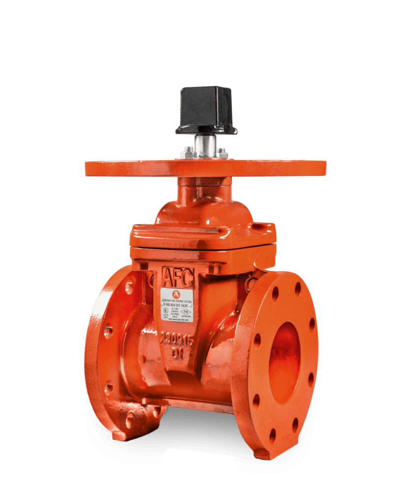
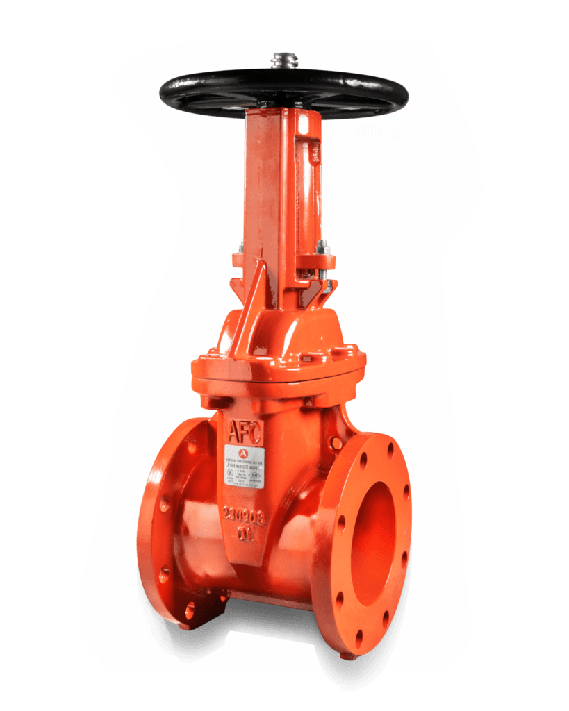
The American Fire Control (AFC) A-3100 NRS Resilient Wedge Fire Gate Valve is designed to control and isolate water flow within fire protection piping systems.
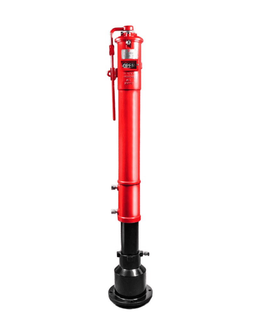
Its Non-Rising Stem construction keeps the external valve height unchanged during opening and closing, making it suitable for installations with limited vertical clearance and for use with an indicator post.
Key Features:
• NRS fire protection gate valve.
• Model A-3100.
• Non-rising stem design.
• Resilient wedge construction for reliable shutoff.
• Suitable for isolating fire protection water lines.
• Equipped with a 2-inch square operating nut.
• Includes an indicator-post mounting plate.
• Triple O-ring stem sealing.
• Ductile iron valve body.
• Ductile iron wedge encapsulated with EPDM.
• Stainless Steel 304 stem.
• Internally and externally fusion-bonded epoxy coated.
• Coating complies with AWWA C550.
• Maximum working pressure of 300 PSI or 21 bar.
• Maximum test pressure of 600 PSI or 42 bar.
• Operating temperature from 0°C to 80°C.
• Available in sizes from 4 to 12 inches.
• UL Listed as shown in the catalogue.
• FM Approved as shown in the catalogue.
• Complies with AWWA C515.
End Connections:
The A-3100 model is supplied with flanged ends compatible with:
• ANSI B16.1 Class 125.
• ANSI B16.42 Class 150.
• BS EN 1092-2 PN16.
Available Sizes:
• 4 inches.
• 6 inches.
• 8 inches.
• 10 inches.
• 12 inches.
Main Construction Materials:
• Valve body: Ductile Iron ASTM A536 65-45-12.
• Resilient wedge: Ductile Iron ASTM A536 with EPDM to ASTM D2000.
• Wedge nut: Stainless Steel 304.
• Stem: Stainless Steel 304.
• Bonnet: Ductile Iron ASTM A536 65-45-12.
• Bonnet gasket: EPDM to ASTM D2000.
• O-rings: EPDM to ASTM D2000.
• Bolts: Stainless Steel 304.
• Lower thrust washer: ASTM B584.
• Upper thrust washer: Stainless Steel 304.
• Square operating nut: Ductile Iron ASTM A536 65-45-12.
• Indicator-post flange: Ductile Iron ASTM A536 65-45-12.
• NPT plug: C95400 Aluminum Bronze.
Operation:
The valve is operated using the square operating nut located at the top of the valve, either directly with a suitable operating wrench or through a vertical indicator post.
Unlike an OS&Y valve, the stem does not rise above the valve body during operation. Valve position is therefore normally indicated by an external indicator post or connected position-indication device.
Applications:
• Automatic sprinkler systems.
• Fire hydrant systems.
• Underground fire water lines.
• External fire protection networks.
• Fire network isolation points.
• Vertical indicator-post installations.
• Commercial and industrial fire protection systems.
• Installations with limited vertical clearance.
Standards and Approvals Shown in the Catalogue:
• UL Listed.
• FM Approved.
• AWWA C515.
• AWWA C550 for the protective coating.
• ANSI B16.1 Class 125.
• ANSI B16.42 Class 150.
• BS EN 1092-2 PN16.
The final valve size and operating arrangement should be selected according to the piping design, installation depth, indicator-post configuration and project requirements.