
MDF IDF room design in a new building is rarely about a single room. A main distribution frame room (MDF) receives the service provider’s lines and houses the network core, and intermediate distribution frame rooms (IDF) on the floors serve the outlets near them. Getting them right starts on the architectural drawings: location, floor area, cooling, power and earthing, the riser route between floors and fire protection. This article is written for consultants and contractors on multi-storey projects and focuses on coordination at shop drawing stage, before the walls are closed.
Key takeaways
- There is usually one MDF, and IDFs are normally one per floor, stacked vertically.
- IDF location is driven by horizontal cable length: TIA guidance gives 90 metres between the room and the work area outlet.
- Water pipes, ductwork and equipment that does not serve telecom should not pass through the room.
- Cooling, clean power and earthing are part of the room design, not add-ons after installation.
- Coordinating these items on the shop drawings costs far less than changing them after finishing works.
In this article
- What is the difference between an MDF, an IDF and a server room?
- Where should IDF rooms go, and how many are needed?
- How much space does a telecom room need?
- Cooling, power and earthing in telecom rooms
- Cable routes between floors (risers)
- Fire protection of the telecom room
- MDF IDF room design checklist before approving shop drawings
- Common mistakes in telecom room planning
- Frequently asked questions
- Conclusion
What is the difference between an MDF, an IDF and a server room?
On site, “network room”, “server room” and “telecom room” are often used for the same space. In multi-storey buildings the roles differ:
| Room | Role in the building | Typical contents |
|---|---|---|
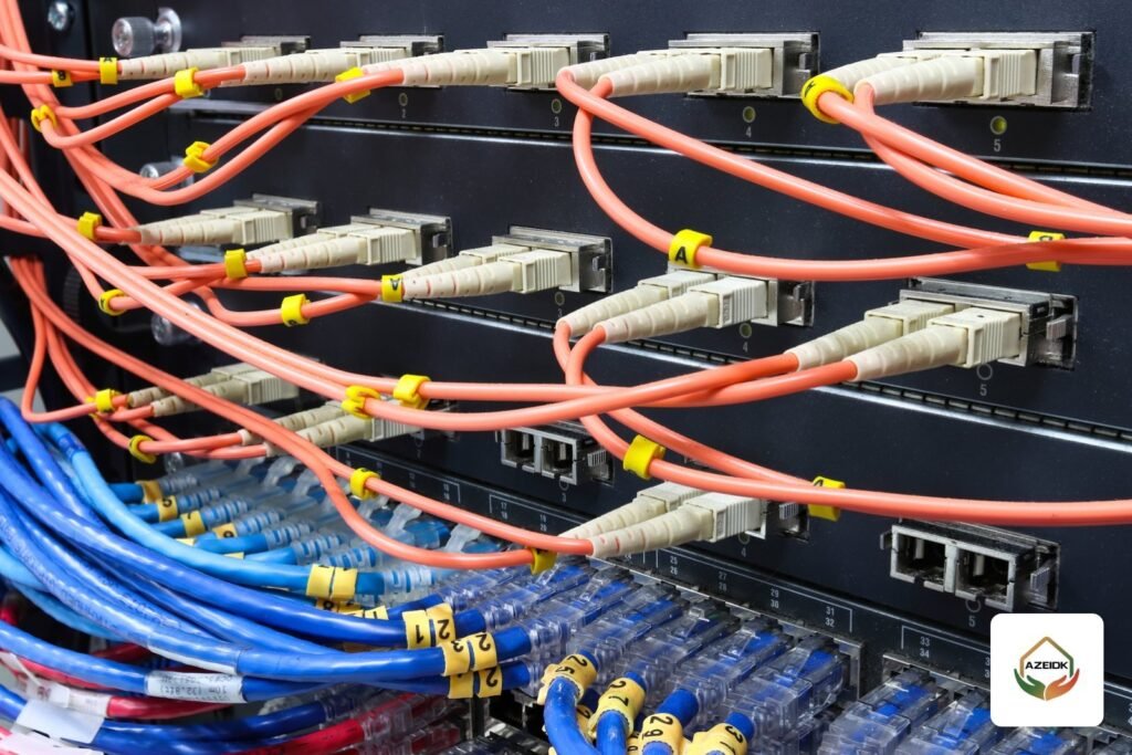
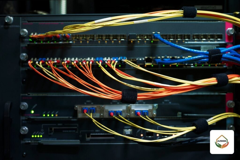
| MDF (main distribution room) | Entrance point for telecom services and the network core | Service provider cables, core switch, router or firewall, fibre patch panels for the riser |
| IDF (intermediate distribution room) | Serves a floor or part of a floor | Floor switches, patch panels, horizontal cable terminations |
| Server room | Runs servers and recorders | Servers, CCTV recorders, storage; may sit inside the MDF in small buildings |
In small facilities one room may hold all of this. In a residential tower or office building, how rooms are spread across floors decides cable lengths, switch count and the cost of the whole package.
Where should IDF rooms go, and how many are needed?
The working rule found in summaries of ANSI/TIA-569 and TIA-568 is one distributor room per floor in multi-storey buildings, stacked so the riser runs straight. The horizontal copper cable distance between the room and the work area is 90 metres, and that figure decides whether a wide floor needs a second IDF.
The designer therefore measures the farthest point on each floor (a car park camera, an access point at the end of a wing, a door reader) from the proposed room along the real cable route, not a straight line. If the route is too long, the room moves to the centre of the floor or another room is added.
How much space does a telecom room need?
Area depends on the number of cabinets and services, but Black Box’s summary of TIA-569-D gives a recommended minimum of about 9 square metres for a backbone room and about 11 square metres for a room that terminates horizontal cabling. It also gives front clearance of at least 1 metre and rear clearance of at least 0.6 metres around cabinets.
On the shop drawing the cabinets are drawn at real size inside the room. For example, a 42U floor cabinet such as the Legrand Linkeo 646760 in the MDF, and smaller wall cabinets such as the AZ Link 12U wall-mount cabinet on floors with few outlets. Door swing, the power board position and the cable tray route above the cabinets are all checked.
Cooling, power and earthing in telecom rooms
Cooling: switches and recorders run continuously and give off heat. The TIA-569-D summary gives an operating range of 5 to 35°C and 8 to 80 percent relative humidity. In Saudi conditions the room usually needs its own air conditioning unit that runs around the clock and does not follow the office AC schedule. This is coordinated with the HVAC contractor as part of the MEP works.
Power: a dedicated circuit from a suitable board, enough outlets for each cabinet, and a UPS protecting critical equipment, for example a Legrand Keor SPE 2200VA, sized for capacity and runtime against the actual load. If the building has a generator, the design states whether the room is on the emergency circuit.
Earthing and bonding: the reference standard for telecom bonding is ANSI/TIA-607. It is implemented with a grounding busbar in the room connected to the building earthing system, with cabinets and metallic cable trays bonded to it.
Cable routes between floors (risers)
The riser is the vertical route linking the MDF to the IDFs. Shop drawings set the number of openings or sleeves in each slab, their sizes and their position in the room. Leaving spare capacity for growth is standard practice, because opening slabs after the concrete is cast is expensive and disruptive.
The riser usually carries fibre between the core and the floor switches, sometimes with copper telephone cables. It must be coordinated with other systems sharing the shaft, such as fire alarm and PA cabling. Any opening through a fire-rated wall or slab is sealed as specified by the consultant and the project’s passive fire protection contractor.
Fire protection of the telecom room
A telecom room is an enclosed space with electrical equipment running all the time. The minimum is smoke detection connected to the building fire alarm system. For MDFs or critical server rooms, the consultant sometimes specifies a gas suppression system instead of, or in addition to, sprinklers, depending on the applicable code and the value of the equipment. These options are covered on our special fire suppression systems page.
The TIA-569-D summary also states that equipment not related to telecom must not be installed in, pass through or enter the room, including piping and ductwork. The coordinated drawing is therefore checked to make sure no drainage or supply pipes run above the cabinets.
MDF IDF room design checklist before approving shop drawings
- MDF location and an IDF on each floor, with horizontal cable lengths checked.
- Room area, cabinet layout, clearances and door.
- Service provider entrance route into the MDF.
- Riser sleeves, sizes and spare capacity.
- Power circuit, outlets, UPS and emergency circuit where provided.
- Dedicated cooling unit with condensate drained outside the room.
- Grounding busbar and bonding of cabinets and trays.
- Smoke detection and suppression if the consultant requires it.
- No water pipes or unrelated services in the room.
At AZEIDK this coordination is part of our shop drawings and coordination service, and cabinets, switches and accessories are supplied under network and communication systems.
Common mistakes in telecom room planning
- Placing the room in whatever space is left on the architectural plan, then finding the farthest outlets exceed the horizontal cable length.
- Locating the room below toilets or kitchens on the floor above, exposing it to water leaks.
- Relying on the general office AC, which switches off after working hours.
- Forgetting riser sleeves in one or more slabs, then core drilling after the pour.
- Leaving no space for an extra cabinet, even though building systems usually grow after occupation.
Each of these can be caught in a drawing review before construction. That is why telecom rooms are best reviewed together with the other ELV systems under our drawings and specifications review service.
Frequently asked questions
What is the difference between MDF and IDF?
The MDF is the main room where service provider lines enter and the network core sits. An IDF is a floor room with the floor switches and the horizontal cable terminations.
How big should a network room be?
It depends on the number of cabinets, but TIA-569-D summaries give a recommended minimum of about 9 to 11 square metres depending on the room type. The final size is set on the shop drawing.
Do I need a telecom room on every floor?
In multi-storey buildings that is the usual arrangement, especially when the farthest outlet on a floor is beyond the allowed horizontal cable length from one room.
Can the server room share the electrical room?
It is not recommended. TIA guidance says the room should not contain equipment that does not serve telecom, and the only electrical equipment allowed is what powers the telecom gear.
What temperature should a telecom room be kept at?
The TIA-569-D summary gives an operating range of 5 to 35°C. In practice the room is designed with dedicated cooling that runs continuously.
Does a telecom room need a fire suppression system?
At minimum it needs detection connected to the fire alarm. Whether a suppression system is needed, and which type, is decided by the consultant based on the applicable code and how critical the equipment is.
Conclusion
MDF and IDF rooms in new buildings are planned from the start: location by cable length, area by cabinets, then cooling, power, earthing, risers and fire protection. All of these belong on the coordinated shop drawing before slabs are cast and walls closed, which saves the project from costly changes after finishing works.
Reviewing the telecom room drawings for a new project? Send the architectural drawings, the number of floors and the expected outlet count, and our team will review them with you. Talk to the AZEIDK team
Related guides
- Fire Protection for Warehouses and Logistics Facilities in Saudi Arabia
- Fire Fighting System Installation in Saudi Arabia: Sprinklers, Hose Cabinets and Pump Room
- Fire System Maintenance Companies in Riyadh: How to Measure Performance and Switch Without a Gap
- Manual Call Points and Audible and Visual Notification Appliances in Fire Alarm Systems