
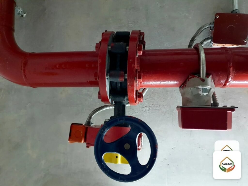
A fire protection butterfly valve is an indicating control valve: a disc turned a quarter turn by a gear operator shuts off the water, a flag shows the valve position, and a built-in switch sends a supervisory signal to the fire alarm panel when the valve leaves the fully open position. Grooved valves suit grooved piping, wafer valves fit between flanges, and an OS&Y gate valve is still required in some places, such as fire pump suction.
AZEIDK supplies the American Fire Control (AFC) grooved fire butterfly valve, models BFG-300 and BFG-301, and the wafer-type BFW-300, in 2 to 12 in sizes rated 300 psi. Below: how the models differ, grooved versus wafer, when OS&Y is the right choice, and switch wiring.
Key takeaways
- BFG-300 and BFG-301 differ by size range: in the FM Approvals record included in the submittal (October 2024 printout), BFG-300 covers 2½ to 8 in and BFG-301 covers 2, 10 and 12 in, both groove x groove at 300 psi.
- AFC butterfly valves have a flag indicator and a built-in supervisory switch, and their FM approval covers aboveground installation only.
- NFPA 20 requires a listed OS&Y gate valve in the fire pump suction pipe; AXA XL guidance warns that a butterfly valve near the suction flange can affect pump performance.
- Weight matters: a 12 in grooved BFG weighs 73 kg, against 153 kg for the grooved AG-3000 OS&Y gate valve of the same size.
In this article
- What is a fire protection butterfly valve and how does it show its position?
- BFG-300, BFG-301 or BFW-300: what is the difference?
- Grooved or wafer: which suits your location in the system?
- When should you choose a fire protection butterfly valve over an OS&Y valve?
- Where is a butterfly valve not the right choice?
- How is the supervisory switch wired to the fire alarm panel?
- What to check in the submittal before supply
- Common mistakes with fire protection butterfly valves
- AFC butterfly valves from AZEIDK
- FAQ
- Conclusion
What is a fire protection butterfly valve and how does it show its position?
FM Approvals Class 1112 (December 2020) covers manually operated indicating valves of the butterfly or ball type that control the water supply to fire protection systems, in sizes from 1 to 12 in, with a minimum rated working pressure of 175 psi. The indicator must show the disc position at all times, and OPEN and CLOSED (or SHUT) must be cast or stamped on the operator cover. For sizes larger than 2½ in, the indicator must be readable from 50 ft (15 m).
On the AFC valves, a worm gear operator with a handwheel turns the disc through 90 degrees, with a flag indicator on top. The disc is EPDM-encapsulated ductile iron for bubble-tight shut-off, and the body is ductile iron ASTM A536 65-45-12 with fusion-bonded epoxy coating to AWWA C550, per the AFC submittal published by AZEIDK.
In the Kingdom, the binding reference is the Saudi Fire Protection Code SBC 801; the 2024 edition of the Saudi Building Code has been mandatory since 30 June 2025. NFPA 13 and NFPA 20 serve as technical references adopted by the designer. NFPA 13 generally calls for listed indicating valves on water supply connections, and a butterfly valve with a position indicator is that type of valve provided the exact model and size are listed; the edition adopted by the designer governs.
BFG-300, BFG-301 or BFW-300: what is the difference?
The difference appears in the FM Approval Guide record included in the submittal (printed 31 October 2024): each model code covers a different set of sizes.
| Item | Grooved BFG-300 / BFG-301 | Wafer BFW-300 |
|---|---|---|
| Connection | Groove x groove, groove dimensions to AWWA C606 | Clamped between flanges compatible with ANSI B16.1 Class 125 and ANSI B16.5 Class 150 |
| Sizes | 2 to 12 in; in the FM record BFG-300 covers 2½, 3, 4, 5, 6 and 8 in, and BFG-301 covers 2, 10 and 12 in | 2 to 12 in; in the FM record BFW-300 covers 2½ to 8 in, and the 2, 10 and 12 in sizes are listed under a different model code |
| Working pressure | 300 psi (21 bar) | 300 psi |
| Design standard | API 609 | MSS SP-67 and API 609 |
| Weight | 7.8 kg (2 in) to 73 kg (12 in) | Not stated on the datasheet |
| Approvals on the datasheet | UL Listed and FM Approved for indoor or outdoor use | UL Listed and FM Approved for indoor or outdoor use |
The UL Product iQ record in the same submittal (Butterfly Valves, category HLXS, file EX28961) names models BFG-300 and BFW-300. For 2, 10 or 12 in valves, confirm that the model code on the submittal and nameplate matches each body’s current official directory.
Grooved or wafer: which suits your location in the system?
Grooved butterfly valve
The valve joins two grooved pipe ends with two grooved couplings, so it needs no flanges or long bolts. It suits risers, floor control stations and branch lines built with grooved pipe. Check that the valve groove (AWWA C606 on the AFC datasheet) matches the groove on the pipe, and that the couplings themselves are listed for at least the system pressure.
Wafer butterfly valve
A slim body is clamped between two pipe flanges by through-bolts, so it is lighter and shorter than a fully flanged valve, and suits pump rooms and flanged lines. Because the through-bolts hold both flanges against the valve body, DeZURIK’s butterfly valve selection paper notes that wafer valves are not recommended for dead-end service without downstream support. Where downstream piping may be removed under pressure, review the alternative with the designer.
If the project flanges follow another standard, such as PN16, do not assume compatibility with ANSI B16.1 Class 125 or B16.5 Class 150; get written confirmation from the supplier before material approval.
When should you choose a fire protection butterfly valve over an OS&Y valve?
Both are acceptable indicating control valves when the model is listed. For the gate valve and its supervision in Saudi projects, see our article on AFC OS&Y gate valves.
| Item | Butterfly valve BFG / BFW | AFC OS&Y gate valve |
|---|---|---|
| Position indication | Flag on the gear operator | Exposed stem length above the handwheel |
| Vertical space | Nothing rises when the valve opens | The stem rises; a 12 in AG-3000 is 1,320 mm tall when open, per its datasheet |
| Weight, 12 in grooved | 73 kg (BFG) | 153 kg (AG-3000) |
| Supervisory switch | Built into the gear operator | Separate switch mounted on the yoke |
| Waterway when open | The disc stays in the flow path; take the equivalent length from listing or manufacturer data | The gate lifts out of the flow path when fully open |
| Fire pump suction | Not suitable | The valve NFPA 20 requires |
In practice, butterfly valves suit floor control stations, branch lines, risers in tight shafts and the pump discharge. OS&Y remains the choice where the specification or the standard requires it.
Where is a butterfly valve not the right choice?
- Fire pump suction: NFPA 20 requires a listed OS&Y gate valve in the suction pipe. Consulting-Specifying Engineer’s explanation, based on the 2013 edition of the standard, says the OS&Y valve is the only device explicitly permitted within 50 ft (about 15 m) of the suction flange, and that a backflow preventer with butterfly valves must be at least 50 ft from the flange. AXA XL links this to disc turbulence affecting pump performance. Check the text of the edition adopted for the project before placing any other device on the suction. On the discharge side, a listed indicating valve, including a butterfly valve, is accepted.
- Buried valves: the FM record for AFC butterfly valves covers aboveground installation only. Underground valves need another arrangement, such as the AFC NRS gate valve A-3100 with the 5100 vertical indicator post.
- Directly against a check valve or reduced-bore fittings: the disc projects beyond the valve body when open. Installation guidelines from one butterfly valve manufacturer (NIBCO) warn of interference when a valve is bolted directly to a check valve outlet or next to lined or heavy-wall pipe, and recommend a spool piece between them.
- Pressures above 300 psi: if the maximum pressure at the valve, including pump churn plus suction pressure, exceeds the valve rating, the answer lies in the design, not the valve.
How is the supervisory switch wired to the fire alarm panel?
FM Class 1112 requires the supervisory switch to operate before the handwheel has turned two full revolutions from fully open, and the wiring diagram and electrical ratings to be marked on the operator cover. The AFC datasheets show two switches inside the gear operator: a supervisory (tamper) switch connected to the supervisory circuit of the fire alarm control panel, and an auxiliary switch for a local bell or horn, plus a green ground lead.
Watch the colours. On the BFG-300/301 diagram the supervisory switch common is white and the auxiliary common is black, while the BFW-300 diagram puts the black common on the panel circuit and the white common on the voltage source and auxiliary device. Wire each valve to its own model’s diagram.
The switch produces a supervisory signal, not a fire alarm, and must be programmed that way; the circuit ends at an end-of-line resistor or the next device. After installation, turn the handwheel off open, confirm the signal, then confirm it restores when the valve is fully open again.
What to check in the submittal before supply
- The model code for each size, matched against the current UL and FM records.
- The end connection: groove dimensions against the approved couplings, or flange standard and class for wafer valves.
- The 300 psi working pressure against the highest pressure at the valve location.
- The installation: aboveground, indoor or outdoor.
- The wiring diagram for both switches and compatibility with the alarm panel and monitor modules.
- Equivalent length or loss coefficient for hydraulic calculations: the published datasheet does not give it, so request it from the manufacturer or the listing data.
Common mistakes with fire protection butterfly valves
- Fitting a butterfly valve on the pump suction because it is smaller and lighter than an OS&Y valve.
- Approving a wafer valve for flanges of a different standard without confirming compatibility.
- Programming the tamper switch as an alarm device, so closing the valve for maintenance triggers a fire alarm.
- Bolting the valve directly to a check valve without confirming disc clearance.
- Tightening flange bolts before confirming the disc moves through its full travel, contrary to installation instructions.
- Accepting a 2, 10 or 12 in valve whose model code does not match the listing record.
AFC butterfly valves from AZEIDK
Through its technical supply service, AZEIDK supplies the AFC grooved butterfly valves BFG-300 and BFG-301 and the wafer BFW-300, with datasheets and UL and FM records, alongside AFC gate, check and ACV-300 alarm valves. For where each valve sits in the system, see our guide to fire protection valves and network components.
FAQ
What is the difference between BFG-300 and BFG-301?
The specifications are the same; the size range differs. In the FM record included in the submittal, BFG-300 covers 2½ to 8 in and BFG-301 covers 2, 10 and 12 in, both grooved at 300 psi.
Can a butterfly valve be installed on the fire pump suction?
Not as the suction valve. NFPA 20 requires a listed OS&Y gate valve in the suction pipe, and AXA XL guidance warns that a butterfly valve within 50 ft of the suction flange can affect pump performance. A listed butterfly valve is accepted on the discharge.
Can a wafer valve be used at the end of a line?
It is not recommended for dead-end service without downstream support, because the flange bolts pass through its body.
Does an AFC butterfly valve need a separate tamper switch?
No. The supervisory switch is built into the gear operator, together with an auxiliary switch. Connect it to the panel’s supervisory circuit following the model’s wiring diagram.
What is the maximum working pressure of AFC butterfly valves?
300 psi (21 bar) for all sizes from 2 to 12 in, with a working temperature of 0 to 80 °C.
Conclusion
Choosing a fire protection butterfly valve starts with its location: grooved on grooved piping, wafer between compatible ANSI flanges, and OS&Y wherever the standard requires it, as on the pump suction. Then match the model code for each size against the UL and FM records, and wire the supervisory switch to the diagram for that model.
Preparing a control valve schedule for your project? Send us the sizes, end connections and location of each valve, and we will propose the right AFC model with datasheets and approval records. Contact the AZEIDK team
Related guides
- CCTV and Access Control Brands in the Saudi Market
- Fire and Security Project Certificates in Saudi Arabia: SABER, UL/FM, LPCB and Local Content
- CCTV Cameras (Security Surveillance Cameras): A Guide to Types, Resolution, Night Vision, Storage and the Saudi Law
- Security Control Room Setup: Video Wall, Operator Workstations, VMS and Operator Staffing