
A fire alarm voltage drop calculation proves that the last sounder on a circuit still receives more than the minimum voltage on its datasheet, even when the standby batteries are at the end of their discharge. The formula is short: total alarm current multiplied by the resistance of the cable out and back. The result depends on wire gauge, circuit length and device current.
Below: where each input comes from, a worked example with Context Plus sounders and Fire World cable in 14, 16 and 18 AWG, and when the fix is another circuit or a separate power supply.
Key Takeaways
- Voltage drop = alarm current × (2 × circuit length × conductor resistance per metre).
- Start from the panel voltage on a depleted battery, not 24 V. The Context Plus CFP panel datasheet gives 20 V minimum on the sounder circuits at final battery voltage.
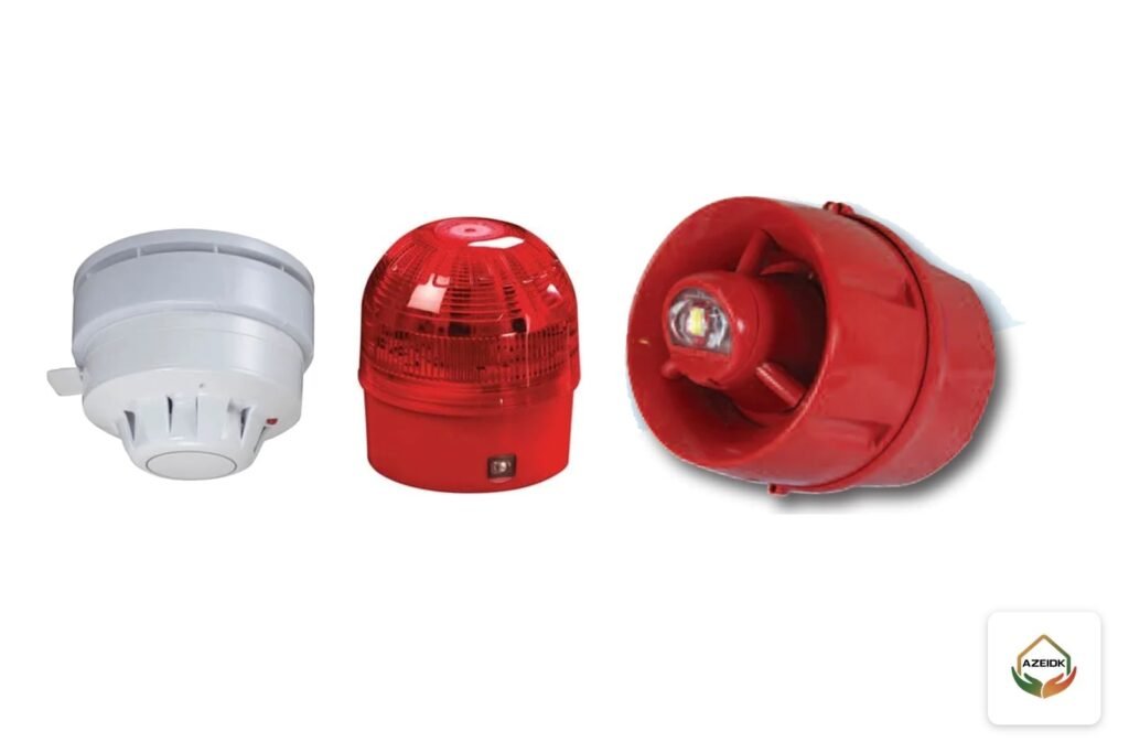
- The end-of-line minimum differs by device: the CP400SR sounder works from 8 to 28 V DC, while the CP450SER sounder/beacon needs 20 to 28 V DC.
- Fire World lists conductor resistance of 8.8, 14 and 22.4 ohm/km for 14, 16 and 18 AWG.
- Addressable sounders are loop powered, so their load belongs in the manufacturer’s loop calculation.
In this article
- Why the Consultant Asks for a Voltage Drop Calculation
- The Fire Alarm Voltage Drop Calculation Formula
- What Voltage to Start From, and What Must Arrive
- Worked Example: Conventional Sounder Circuit on a CFP Panel
- Addressable Sounders on the Loop Are a Different Calculation
- 14 vs 16 vs 18 AWG: Resistance and Approximate Maximum Length
- Fire World or Falcon Gold Cable: What to Take from the Datasheet
- When You Need Another Circuit or a NAC Booster
- Common Voltage Drop Mistakes
- How to Check the Calculation Before the Approval File Goes In
- Frequently Asked Questions
- Conclusion
Why the Consultant Asks for a Voltage Drop Calculation
The Saudi Fire Code, SBC 801, refers fire alarm installation to NFPA 72 in section 907.2. NFPA 72 Chapter 7, the documentation chapter added in the 2013 edition, lists the minimum documents for a system, including battery calculations and voltage drop calculations, as EC&M explained in January 2026.
In Saudi projects the calculation usually sits in the design file the consultant reviews for Civil Defense approval, next to the drawings, battery calculation, datasheets and material submittal. At commissioning, voltage is normally measured at the furthest device.
The Fire Alarm Voltage Drop Calculation Formula
Current leaves the panel on one conductor and returns on the other, so the run length is doubled:
- Circuit resistance (ohm) = 2 × length in km × conductor resistance (ohm/km).
- Voltage drop (V) = total alarm current (A) × circuit resistance.
- Voltage at the last device = starting voltage − voltage drop, which must stay above the datasheet minimum.
Lumping the whole load at the end gives the highest possible drop. With devices evenly spread the real drop is close to half that, but proving it needs a segment-by-segment calculation.
Take alarm current from the datasheet at the volume setting you will actually use. In the Context Plus FirePlus catalogue, the CP550DB sounder rises from 8.3 mA on low to 30.8 mA on high.
What Voltage to Start From, and What Must Arrive
Starting voltage: the battery at end of discharge
The worst case is an alarm at the end of the standby period after a mains failure. In US practice, 20.4 V is used as the starting voltage on 24 V systems; SDM Magazine notes that UL 864 treats 20.4 V as the end of the battery’s useful life, and California’s HCAI PIN 63 uses the same figure for panel output on a depleted battery. For EN 54 equipment, use the panel’s own datasheet: Context Plus CFP conventional panels state a sounder circuit alarm voltage of 27 V maximum and 20 V minimum at final battery voltage.
The minimum at the last device
There is no single value. SDM puts UL-listed appliances at 16 to 33 V. Context Plus conventional devices vary: the CP400SR works from 8 to 28 V DC at 13 mA (24 V DC), and the CP450SER sounder/beacon works from 20 to 28 V DC only.
Worked Example: Conventional Sounder Circuit on a CFP Panel
Datasheet inputs: each CFP sounder circuit has a resettable fuse with a 200 mA minimum hold current, a 500 m maximum cable length and a minimum conductor size of 1 mm². The CP400SR draws 13 mA.
- Load: 15 × 13 mA = 195 mA, or 0.195 A (a sixteenth sounder brings it to 208 mA, above 200 mA).
- Length: 500 m, with the load lumped at the end.
- Starting voltage: 20 V from the panel datasheet.
| Wire gauge | Circuit resistance (2 × 0.5 km) | Drop at 0.195 A | Voltage at last sounder |
|---|---|---|---|
| 14 AWG (8.8 ohm/km) | 8.8 ohm | 1.72 V | 18.28 V |
| 16 AWG (14 ohm/km) | 14.0 ohm | 2.73 V | 17.27 V |
| 18 AWG (22.4 ohm/km) | 22.4 ohm | 4.37 V | 15.63 V |
All three gauges leave far more than 8 V at the last CP400SR, so the circuit passes on voltage. But 18 AWG has a cross-section of only 0.823 mm², below the 1 mm² minimum in the panel datasheet, so it is ruled out for this panel even though the voltage is adequate. With the sounders evenly spread, the 16 AWG drop falls from 2.73 V to about 1.46 V.
What if the devices are CP450SER?
The starting voltage is 20 V and the device minimum is 20 V, so the available drop at final battery voltage is zero. Any cable length leaves the last device below 20 V. The answer is to revisit the device or the power source with the manufacturer, not a larger wire. The CP450SER product page does not state its current draw, so get that figure from the supplier before calculating.
Addressable Sounders on the Loop Are a Different Calculation
Context Plus addressable sounders are loop powered and need no separate sounder circuit. Per the datasheet, the CON431A draws 5 mA in alarm, the CON458A beacon 10 mA, and the CON456A sounder/beacon and CON433A 14 mA, all with 550 µA quiescent current.
The XFP panel datasheet says its loop drivers support up to 40 loop-powered 10 mA sounders per loop (400 mA), with a maximum loop output of 500 mA at 25 V minimum and 34 V maximum. Forty CON456A units draw 560 mA, more than the loop maximum before any detectors or modules are added, so they must be split across loops and checked with the loop and battery calculation tool the datasheet refers to.
To show the scale only: a 500 m loop in 16 AWG has 14 ohm of resistance. With 400 mA lumped at the end, the drop is 5.6 V; with 40 devices spread evenly, about 2.87 V. Judging the result needs the loop device voltage limits from the panel manual and the manufacturer’s tool. For device and isolator layout, see our addressable loop design guide.
14 vs 16 vs 18 AWG: Resistance and Approximate Maximum Length
The table gives the maximum one-way circuit length with the load lumped at the end and a 4 V allowable drop, for example starting at 20 V with a device that needs 16 V. The first figure uses Fire World resistance; the second uses the NEC table value for solid copper at 75°C.
| Gauge | Area (mm²) | Resistance (ohm/km) Fire World / NEC 75°C | Max length at 0.2 A | At 0.5 A | At 1 A |
|---|---|---|---|---|---|
| 14 AWG | 2.08 | 8.8 / 10.1 | 1,136 / 990 m | 455 / 396 m | 227 / 198 m |
| 16 AWG | 1.31 | 14.0 / 16.0 | 714 / 625 m | 286 / 250 m | 143 / 125 m |
| 18 AWG | 0.823 | 22.4 / 25.5 | 446 / 392 m | 179 / 157 m | 89 / 78 m |
Maximum length = allowable drop ÷ (current × 2 × resistance per metre). Resistance rises with temperature and the Fire World page gives no reference temperature, so the NEC column is the more conservative check. The panel’s maximum circuit length (500 m on the CFP) is a separate limit.
Fire World or Falcon Gold Cable: What to Take from the Datasheet
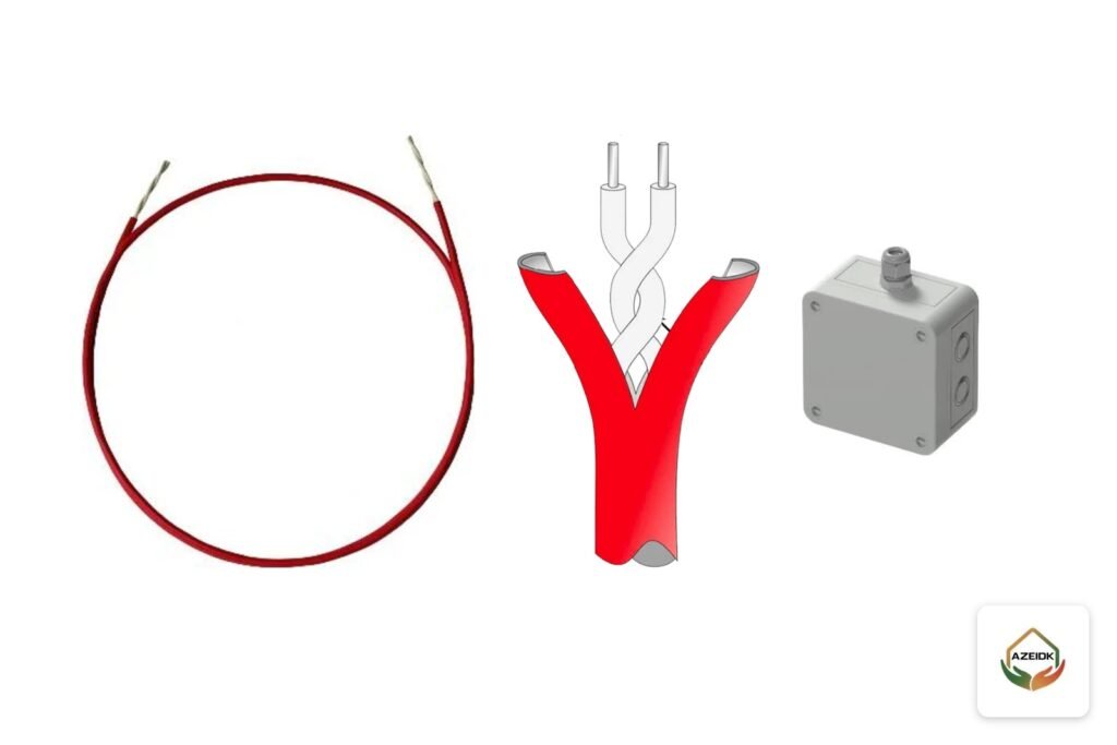
Fire World FPLR shielded cable comes in 14, 16 and 18 AWG with solid bare copper conductors, and its page lists the resistance of each size, so the value goes straight into the calculation.
The Falcon Gold 2-core shielded cable comes in 16 and 18 AWG with copper-clad aluminium (CCA) conductors. Its page gives no resistance value, and aluminium is more resistive than copper, so ask the supplier for the measured resistance per km rather than using copper tables. For cable types and fire-resistance grades, see fire alarm cable types.
When You Need Another Circuit or a NAC Booster
- Current exceeds the circuit rating: move devices to another panel circuit; the CFP has four sounder circuits totalling 800 mA.
- The last device is below its minimum voltage: try a larger gauge first, then shorten the run by feeding from the middle or splitting it into two branches.
- Total alarm current exceeds the panel supply or battery: this is where a separate NAC booster power supply near the load fits, with its own battery sizing.
After any split, rerun the battery sizing, because total alarm current drives battery capacity. The steps are in the fire alarm battery calculation guide.
Common Voltage Drop Mistakes
- Starting from 24 V or 27 V instead of the final battery voltage.
- Using one-way length and forgetting the return conductor.
- Taking sounder current at the lowest volume, then setting it to high on site.
- Applying 16 V to every device when some need 20 V.
- Using copper resistance for a CCA cable.
- Ignoring the minimum conductor size and maximum circuit length on the panel datasheet.
- Adding devices on site without updating the calculation.
How to Check the Calculation Before the Approval File Goes In
The AZEIDK GROUP engineering design and calculations service covers battery and load calculations for alarm systems, design to SBC 801 and NFPA 72, and a stage for reviewing and updating outputs. When you prepare a voltage drop calculation for review, make sure the file shows:
- The starting voltage and where it comes from (panel datasheet or the practice adopted for the project).
- Each device model, its current at the actual setting, and its minimum voltage.
- Each circuit length from the drawings, plus the cable gauge and resistance from its datasheet.
- The result for each circuit against the device minimum and the panel limits.
Browse panels and devices under fire alarm systems.
Frequently Asked Questions
How do I calculate voltage drop on a sounder circuit?
Multiply total alarm current by the out-and-back resistance, subtract it from the final battery voltage and compare with the device minimum.
What is the maximum allowable voltage drop for a fire alarm?
There is no fixed percentage. It is the starting voltage at end of discharge minus the last device’s minimum operating voltage.
Is 18 AWG wire acceptable for notification circuits?
On short, light circuits the voltage may be fine, but the CFP panel requires 1 mm² and 18 AWG is only 0.823 mm².
Why use 20.4 V instead of 24 V?
An alarm may come after a power failure with discharged batteries. 20.4 V is common with UL panels; for EN 54 panels use the panel datasheet.
Do addressable sounders need a voltage drop calculation?
Yes, within the whole loop calculation with detectors and modules, using the manufacturer’s tool.
How does CCA cable change the calculation?
CCA has higher resistance than copper of the same gauge, so use the supplier’s measured resistance, not copper tables.
Conclusion
Voltage drop is one formula fed by three datasheets: the panel’s final voltage, the device current and minimum voltage, and the cable resistance. In our example, 16 AWG serves fifteen CP400SR sounders over 500 m, while the CP450SER leaves no margin at final battery voltage. Check every circuit with its real values before fixing the wire gauge.
Preparing the fire alarm calculation file for your project? Send the drawings, panel and device models and cable type, and our team will review the load and voltage drop calculations with you. Contact the AZEIDK GROUP team
Related guides
- Intercom for Villas and Apartment Buildings in Saudi Arabia: Audio, Video, IP and Mobile App (Hikvision and Dahua)
- Halon Extinguisher: Why It Was Phased Out and What Replaces It in Saudi Arabia
- Residential Compound Security Systems: Gates, Intercom, CCTV and Access Control in One Design
- Fire Safety in Office and Administrative Buildings