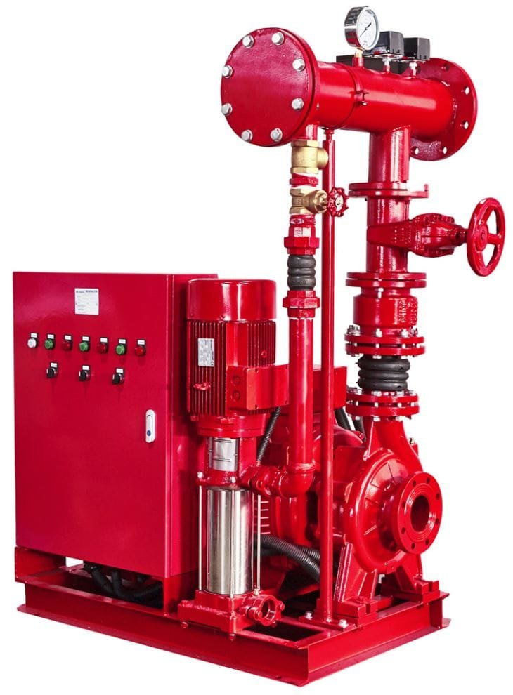

Transformer fire protection at substations, factories and malls usually relies on a fixed water spray system released by a deluge valve through open nozzles. NFPA 15 (2027 edition) requires spray impingement on every exposed exterior surface of the transformer at no less than 10.2 L/min/m² (0.25 gpm/ft²), protection of the non-absorbing ground around it, and safe clearances from live electrical parts.
This article covers the oil-filled transformer application specifically: how the density is calculated, where nozzles go and where spray is not allowed, how detection is chosen, why oil containment is designed together with the system, and what is tested at handover and during maintenance. For how a deluge valve works in general, see our article on the deluge sprinkler system, valve and nozzles. AZEIDK GROUP delivers these systems as part of its fire fighting systems in Saudi Arabia.
Key Points
- The current edition of NFPA 15, Standard for Water Spray Fixed Systems for Fire Protection, is the 2027 edition. It covers design, installation and acceptance testing of fixed water spray systems.
- Minimum density on the transformer and its appurtenances is 10.2 L/min/m² (0.25 gpm/ft²) over the projected area of the enclosing rectangular prism, plus 6.1 L/min/m² (0.15 gpm/ft²) on the non-absorbing ground where oil may spread.
- Spray piping is not routed across the top of the tank or the face of the transformer cabinet, and nozzles must not envelop energized bushings or lightning arresters unless the manufacturer and owner allow it.
- Clearance from live parts comes from the electrical clearance table in the standard, based on the basic impulse insulation level (BIL), with an adjustment for altitude.
- The system needs oil containment and a safe drainage path for fire water, plus an annual full flow trip test with the main strainer flushed afterwards.
In this article
- Why do oil-filled transformers need dedicated protection?
- Which NFPA 15 edition applies, and how is it used in Saudi projects?
- How is the water spray density for transformers calculated?
- Where do nozzles go, and where is spray not allowed?
- Electrical clearances between the system and live parts
- Detection and deluge valve release
- Oil containment and fire water drainage
- Where these systems are used in Saudi Arabia
- Acceptance testing and periodic maintenance
- Common design and installation mistakes
- How AZEIDK GROUP supports a transformer protection project
- Frequently Asked Questions
Why do oil-filled transformers need dedicated protection?
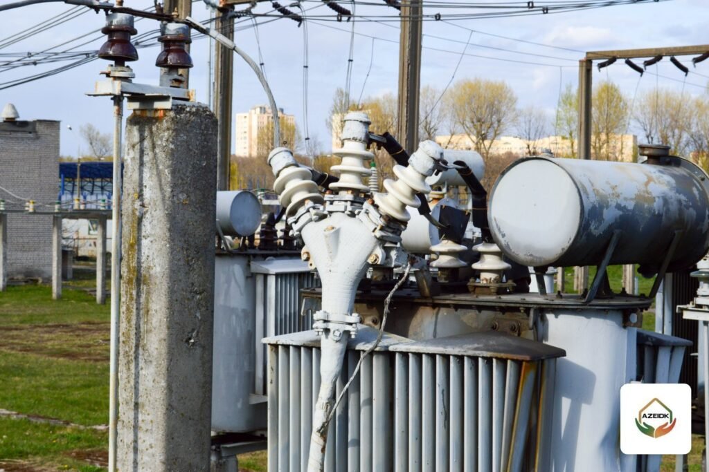
An oil-filled transformer holds a large volume of insulating oil in a steel tank. An internal winding fault can raise the pressure until the tank ruptures or a bushing fails, releasing hot oil that burns on the transformer and on the ground around it. This is a flammable liquid fire that spreads with the spill and exposes nearby equipment and buildings to intense radiant heat.
Ceiling sprinklers do not address this, and large units are usually outdoors anyway. NFPA 15 lists four design objectives for water spray: extinguishment, control of burning, exposure protection and prevention of fire. For transformers the practical aim is usually to control burning, cool the unit and protect its surroundings until the power is isolated.
Which NFPA 15 edition applies, and how is it used in Saudi projects?
The edition currently sold by standards distributors is NFPA 15-2027. It sets requirements for the design, installation and acceptance testing of fixed water spray systems, plus periodic testing of ultra high-speed water spray systems. Its transformer section (7.4.4) is the reference for density and nozzle arrangement.
In the Kingdom, the Saudi Fire Protection Code SBC 801 and Civil Defense requirements remain the regulatory framework. NFPA 15 is a technical reference that the designer adopts, writes into the specification and the reviewing authority or consultant checks. Power generation sites also use NFPA 850 for transformer separation and barrier walls, and the owner or insurer may add their own requirements. Good design starts by confirming which reference the contract adopts.
How is the water spray density for transformers calculated?
NFPA 15 requires complete spray impingement on all exposed exterior surfaces. Water quantity is based on the rectangular prism that encloses the transformer and its appurtenances, not on the true area of the fins and radiators.
| Protected area | Minimum density | Design note |
|---|---|---|
| Transformer and appurtenances (tank, radiators, conservator, pumps) | 10.2 L/min/m² (0.25 gpm/ft²) | Over the projected area of the enclosing rectangular prism |
| Non-absorbing ground exposed to oil spread | 6.1 L/min/m² (0.15 gpm/ft²) | Check where the ground is concrete or paved without a drainage pit |
| Conservator tank and special configurations | Same density as the transformer | One of the most frequently missed items on drawings |
A simple worked example
Take an enclosing prism of 4 m by 3 m by 3.5 m high. The top is 12 m², the long sides 28 m² and the short sides 21 m², a total of 61 m². At 10.2 L/min/m² the transformer needs about 622 L/min. If 40 m² of non-absorbing concrete surrounds it, add about 244 L/min at 6.1. This is only the theoretical minimum: actual flow rises once nozzles are selected, overlap is allowed for and pressure at the most remote nozzle is calculated, which is done through engineering design and hydraulic calculations, not by estimate.
Where do nozzles go, and where is spray not allowed?
Transformer systems use open water spray nozzles on pipe rings around the unit so that every face receives direct impingement. NFPA 15 and the Viking deluge design manual set several practical rules:
- Top surface: nozzles are aimed to sweep water across the top of the tank and wash off pooled oil.
- Piping over the unit: spray piping is not routed across the top of the tank or across the face of the cabinet, unless impingement cannot be achieved otherwise and the required electrical clearance is kept.
- Bushings and lightning arresters: nozzles are placed so the spray does not envelop energized bushings or arresters by direct impingement, unless the manufacturer or its literature and the owner authorize it.
- Conservator, pumps and radiators: need the same density.
- Strainers: a main line strainer is required where nozzle waterways are smaller than 9.5 mm (3/8 in), and individual strainers where a nozzle waterway is smaller than 5 mm (3/16 in).
Outdoors, wind affects the spray pattern, so nozzle angle, K-factor and distance to the surface come from that nozzle’s approved datasheet, not from a previous project.
Electrical clearances between the system and live parts
NFPA 15 tabulates the minimum distance between any part of the spray system (pipe, nozzles, supports) and uninsulated live parts, by system voltage and basic impulse insulation level (BIL). Higher BIL means larger clearance. The standard also adjusts clearances for altitude, which matters for projects in high cities such as Abha and Taif.
In practice the BIL comes from the transformer nameplate or the electrical engineer, clearances are drawn on the shop drawings before fabrication and checked on site after installation. The owner of the electrical system should define how the transformer is tripped when the system operates; that is an electrical operating decision coordinated with the fire designer.
Detection and deluge valve release
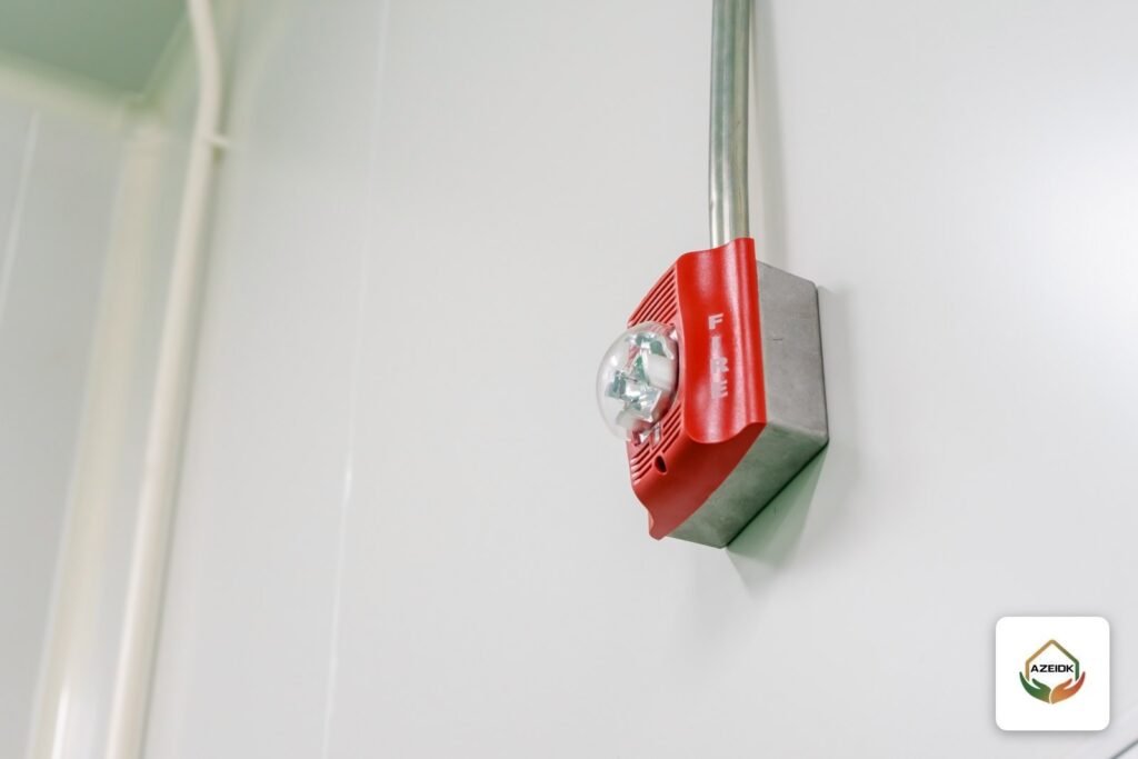
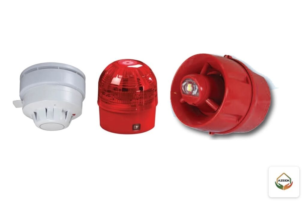
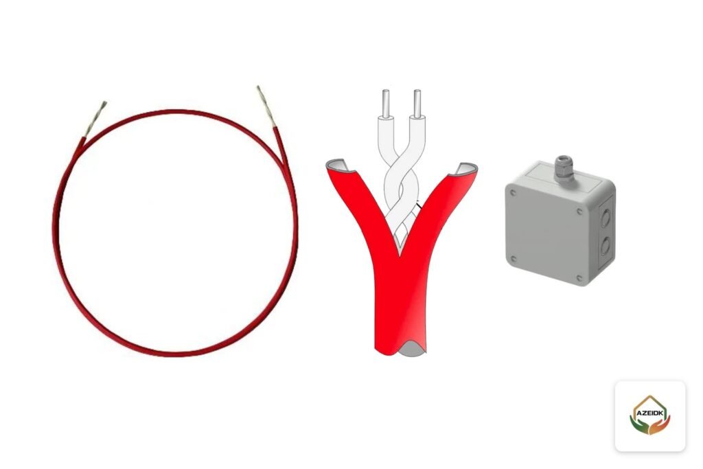
The deluge valve opens water to all open nozzles at once and is released by a separate detection system. Typical options for outdoor transformers:
| Detection | How it works | Transformer notes |
|---|---|---|
| Linear heat detection cable | Heat-sensitive cable looped around the unit | Suits irregular outdoor equipment |
| Rate-compensated heat detectors | Fixed temperature with compensation for fast heat rise | Described by Viking as very reliable for exterior transformer protection |
| Pilot sprinklers on a pneumatic or hydraulic line | An operated pilot head drops pressure and trips the valve | Mechanical release independent of a panel |
| Manual release | Manual station at the valve or remote | Provided alongside automatic release |
Smoke and beam detectors are not suited to outdoor exposure, and Viking notes that outdoor spacing of fixed-temperature or rate-of-rise detectors is reduced by at least 50% from smooth-ceiling listings. See also heat detector types and installation and Cla-Val valves including the 134-05 deluge valve.
Oil containment and fire water drainage
Spray alone is not enough without control of spilled oil. AXA XL guidance places the transformer over a curbed basin filled with clean, coarse crushed stone of about 25 to 38 mm, deep enough to hold all the oil from the units in it, with drainage that keeps fire water and burning oil away from nearby property.
A recurring problem is a basin sized for oil only, which overflows once spray water for the discharge duration is added. Basin volume or drainage routing should be coordinated between the fire and civil designers, with an oil separator before the drainage network. Where a barrier wall separates two units, T&D World notes that it should extend at least 0.31 m (1 ft) above the top of the tank and conservator and 0.6 m (2 ft) beyond the transformer and radiators, or to the edge of the containment, whichever is greater.
Where these systems are used in Saudi Arabia
Water spray for transformers appears at substations inside factories and industrial cities, outdoor transformers serving malls, large compounds and hospitals, and power generation sites. The answer depends on the site: a well-separated outdoor unit may rely on spatial separation and containment, while one close to a building or critical equipment needs water spray, a barrier wall or both. Dry-type and indoor transformers are covered under electrical room fire protection. For industrial projects see industrial facilities.
Dust and wind on open sites mean nozzles may need blow-off caps that release with flow, and checking nozzle direction and cleanliness becomes a routine maintenance item.
Acceptance testing and periodic maintenance
Before handover the piping is flushed, hydrostatically tested to the acceptance requirements of the standard, and given a full operating test: detection is actuated, response time measured, spray coverage and pattern verified on all surfaces and pressure at the most remote nozzle recorded. These steps are part of testing, commissioning and handover.
Maintenance then follows NFPA 25. The table summarizes the items in the City of Henderson water spray inspection form, which is based on NFPA 25:
| Frequency | Inspect or test |
|---|---|
| Monthly | Control valve position and supervision, deluge valve exterior and trim, nozzle direction, condition and blow-off caps |
| Quarterly | Drainage trenches and trap sumps clear, pipe and hangers, water motor gong |
| Semiannual | Supervisory switches and alarm devices |
| Annual | Full flow trip test with spray pattern and remote nozzle pressure, detection response time, main drain test, control valves operated through full travel, main strainer flushed after the test, deluge valve interior cleaned |
| Five-year | Strainer basket removed and inspected for corrosion |
The annual flow test is scheduled with site operations because water will reach the transformer. These items fit into annual maintenance contracts with clear records for every visit.
Common design and installation mistakes
- Calculating density on the main tank only and missing the conservator, radiators and pumps.
- Running a pipe ring over the top of the transformer for convenience.
- Using indoor heat detector spacing on an outdoor unit.
- Sizing the containment for oil only, or draining straight to the network without an oil separator.
- Leaving electrical clearances off the drawings, so problems are found after installation.
- Not flushing the main strainer after the flow test, so small nozzles block at the next operation.
How AZEIDK GROUP supports a transformer protection project
AZEIDK GROUP provides deluge systems as part of its fire fighting solutions in Saudi Arabia: confirming the adopted reference, hydraulic calculations, selection of nozzles, deluge valve and detection, technical supply with datasheets for each component, installation, acceptance testing and periodic maintenance. We start by asking for transformer data (dimensions, oil volume, voltage and BIL, distance to nearby buildings), because every calculation depends on it.
Frequently Asked Questions
What water spray density does NFPA 15 require for transformers?
At least 10.2 L/min/m² (0.25 gpm/ft²) over the projected area of the rectangular prism enclosing the transformer and appurtenances, and 6.1 L/min/m² (0.15 gpm/ft²) on non-absorbing ground exposed to oil spills.
What is the current edition of NFPA 15?
The current edition is NFPA 15-2027. Always confirm the edition named in the project specification or adopted by the reviewing authority.
Can water be sprayed directly on transformer bushings?
Nozzles are normally positioned so that spray does not envelop energized bushings or lightning arresters. Direct impingement is allowed only when the manufacturer and the owner authorize it.
Which detector suits a deluge system on an outdoor transformer?
Linear heat detection cable, rate-compensated heat detectors or pilot sprinklers are common. Smoke and beam detectors are not suited to outdoor exposure.
Is a containment basin sized for the oil volume enough?
It must hold at least all the oil in the units it serves, then be checked against spray water flow, drainage routing and the oil separator so it does not overflow during discharge.
How often is a transformer water spray system flow tested?
A full flow trip test is carried out annually, checking spray pattern and remote nozzle pressure, and the main strainer is flushed afterwards.
Have an oil-filled transformer that needs water spray, or an existing system to review? Send us the transformer dimensions, oil volume, BIL and site plan, and we will review density, detection and containment with you before design. Contact the AZEIDK GROUP team
Related guides
- Fingerprint Attendance Device Price in Saudi Arabia: What Drives the Cost (Fingerprint or Face, Headcount, Software, Installation) and How to Compare Quotes
- Saudi Building Code: SBC Parts from SBC 201 to SBC 1401, the 2018 and 2024 Editions, What “2021” Means, and Where to Get the Official Copy
- Foam Fire Suppression for Saudi Industrial Facilities: Types and Applications
- Fail Safe vs Fail Secure: Do Electronic Doors Open in a Fire or Power Cut?