
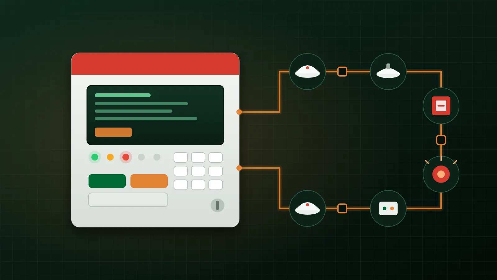
In an addressable system, knowing how many detectors you need is only the start. How you split them across addressable fire alarm loops, where the isolators go, and the cable length and electrical load on each loop decide how many devices one cable short will take out, and whether the drawings get through review.
This guide covers loop capacity, isolator spacing and device distribution. It draws on the official datasheets for the Context Plus addressable fire alarm systems supplied by AZEIDK, and on NFPA 72 as a technical reference. For the choice between conventional and addressable systems, see our conventional vs addressable selection guide.
Key takeaways
- Every loop has four limits at once: addresses, loop current, cable length and resistance, and the number of loop-powered sounders.
- On Context Plus XFP panels a loop takes up to 126 addressable devices, 500mA maximum current, up to 1 km of cable and no more than 20 Ω per conductor.
- The manufacturer’s catalogue calls for an isolator at least every 20 devices and at structural fire barriers and zone boundaries.
- NFPA 72 defines pathway Classes A, B and X by how a circuit behaves under opens, shorts and ground faults.
- Cable size and type come from the panel datasheet, not from site habit.
In this article
- What drives the design of addressable fire alarm loops?
- NFPA 72 pathway classes: A, B and X
- Loop capacity: four limits, not one
- Isolators: where they go and why
- Distributing devices across loops
- Loop cable and routing
- Practical loop design steps
- Common loop design mistakes
- Context Plus addressable panels and devices from AZEIDK
- Frequently asked questions
- Conclusion
What drives the design of addressable fire alarm loops?
An analogue addressable loop is a two-conductor cable that leaves the panel, runs through the detectors, manual call points, sounders and modules, and returns to the panel. The panel polls each device by address, so it knows exactly where an alarm or fault is. On XFP panels, for example, the catalogue lists auto-polling from each loop end and onboard loop isolators with LED indication when active.
In Saudi Arabia the regulatory frame is the Saudi Fire Protection Code, SBC 801. Its 2024 edition has been mandatory since 30 June 2025 and covers detection and alarm within its fire protection and life safety chapters. The General Directorate of Civil Defense oversees how the code is applied, and facilities are licensed through the Salamah platform. Designers use NFPA 72 (current edition 2025) as the technical reference for circuit details, to the extent the design adopts it or the project documents and the authority require it.
NFPA 72 pathway classes: A, B and X
NFPA 72 Chapter 12 covers circuits and pathways. It classifies them by performance under fault conditions and also sets pathway survivability levels for fire conditions. The table summarises the classes most used for signaling line circuits (SLCs), as described in technical articles in Security Sales & Integration and Electrical Contractor on Section 12.3 of NFPA 72. Check the text of the edition adopted for the project:
| Class | Redundant path | Behaviour under fault | What it means for design |
|---|---|---|---|
| Class B | No | Operation stops beyond an open; a single ground fault is annunciated without loss of operation | Simplest and least cable, but one open drops everything after it |
| Class A | Yes | Operation continues past a single open, with a trouble signal | The cable must return to the panel |
| Class X | Yes | Operation continues past a single open, a single short, or an open combined with a ground fault | In practice needs isolators, often built into the devices |
The designer sets the class for each circuit and records it on the drawings and specifications. A loop that returns to the panel is not automatically Class X. What counts is how many isolators there are, where they sit, and what the device installation manuals confirm.
Loop capacity: four limits, not one
A common mistake is to size a loop by address count alone. Check all of these limits and work to the lowest:
- Addresses: 126 devices per loop on XFP and FirePlus, and 127 per loop on XP95 protocol for ZFP, per each panel’s datasheet.
- Loop current: 500mA maximum per loop on XFP, ZFP and FirePlus. Add up quiescent and alarm currents from each device’s datasheet.
- Loop-powered sounders: the XFP catalogue allows up to 40 sounders at 10mA per loop. Higher-output sounders draw more, so the number falls.
- Cable: up to 1 km per loop, no more than 20 Ω per conductor and no more than 0.27µF cable capacitance on XFP and ZFP.
| Item | XFP | ZFP | FirePlus |
|---|---|---|---|
| Loops | Single loop on the two models listed on the AZEIDK site (16 and 32 zone) | 1, 2, 4, 6 or 8 by model and cabinet size (manufacturer catalogue) | 1 to 6 by model |
| Devices per loop | 126 | 127 (XP95) | 126 |
| Max loop current | 500mA | 500mA | 500mA |
| Loop cable | Fire resistant, screened, 1 mm² minimum | Fire resistant, screened, up to 2.5 mm² | 1.5 to 2.5 mm² |
| Max loop length | 1 km | 1 km | 1 km |
| Stated approval | EN 54-2 and -4, LPCB | EN 54-2 and -4, Intertek | Per the product page: the UL certificate in the submittal lists models ULP-CON1L to ULP-CON4L only |
These values come from the datasheets and catalogue published on the AZEIDK website. Check them for the exact model before approval. The FirePlus page lists ULP-CON5L and ULP-CON6L in the product schedule, but the UL certificate in the submittal does not name them, so confirm the required approval before specifying a five or six loop panel.
Isolators: where they go and why
An isolator cuts off the shorted section of a loop so the rest keeps working. The datasheet for the XPERT Style isolating base, model 45681-284IMC, describes it as loop powered. On a short circuit or abnormally low impedance it isolates the negative supply in the direction of the fault, then restores power automatically once the fault clears. The detector fitted to the base stays active during isolation.
Spacing rule
The XFP catalogue calls for isolators at intervals of no more than 20 devices, and at the building’s structural fire barriers and zone boundaries. The isolating base datasheet adds that the total switch-on surge current of the devices between isolators must not exceed 20mA. The page for the 55000-720 loop isolator gives the same figure: 20 detectors, or their equivalent load.
What NFPA 72 says about device loss
According to SecurityInfoWatch, quoting the 2016 edition of NFPA 72, a single fault on a pathway serving addressable devices must not cause the loss of devices in more than one zone, with each floor treated as a separate zone for this purpose. The 2013 edition used a fixed cap of 50 devices instead. Check the text of the edition the project adopts. On site, this means a loop that serves more than one floor needs isolation at each floor boundary.
Devices with built-in isolators
AZEIDK supplies Context Plus devices with built-in isolators, including the SA5900-908IMC manual call point, the SA4700-102IMC input/output unit, the 55000-845IMC zone monitor, the 55000-852IMC sounder controller and the CON456A/CX/W sounder-beacon base. The datasheets for the input/output, zone monitor and sounder controller units describe a bi-directional isolator that is unaffected by a single short on either the loop input or output.
Distributing devices across loops
- Follow the fire boundaries: give each floor or fire compartment its own loop, or place an isolator wherever the loop crosses a fire barrier or zone boundary.
- Leave spare capacity: do not fill a loop to the last address or the last milliamp. Architectural changes add devices. Set the spare percentage in the project specification.
- Split heavy loads: where there are many sounders and beacons, spread them over several loops, use the panel’s conventional sounder circuits, or use a sounder controller with an external supply.
- Conventional devices on the loop: the 55000-845IMC zone monitor controls a zone of up to 20 Series 65 conventional detectors, per its datasheet.
- Apartments: the XFP508X hush button is limited to 20 units per loop, per its datasheet.
- Special detectors: addressable heat, beam and flame detectors count as addresses and loads on the same loop. For heat detector applications, see our guide to Context Plus addressable heat detectors.
Loop cable and routing
The XFP catalogue specifies fire resistant, screened cable with a minimum conductor size of 1 mm². The FirePlus page specifies 1.5 to 2.5 mm². So check the cable you buy against the panel datasheet before ordering. An 18 AWG conductor is about 0.82 mm², below the XFP minimum. 16 AWG (about 1.31 mm²) and 14 AWG (about 2.08 mm²) are above it, although 16 AWG falls below the 1.5 to 2.5 mm² range on the FirePlus page.
Work out resistance from the actual loop length, including drops to devices and the return to the panel, multiplied by the resistance per kilometre on the cable datasheet. Confirm it stays below 20 Ω per conductor. Good practice is to route the return leg separately from the outgoing leg, so that a single incident cannot cut both.
Where the project documents call for pathway survivability during a fire, the designer selects fire resistant cable or equivalent protection. For cable types and how they differ, see our fire alarm cables guide. Once loop loads are fixed, the next step is the fire alarm battery calculation.
Practical loop design steps
- Mark fire zones, floors and fire barriers on the architectural drawings.
- Lay out detectors, call points and notification appliances to the approved design.
- Choose the pathway class (B, A or X) for each circuit as the project documents require.
- Assign devices to loops by floor and fire zone.
- Place isolators at least every 20 devices and at every zone boundary or fire barrier.
- Total the addresses, current and sounder count on each loop, compare them with the datasheet limits and leave spare capacity.
- Calculate cable length and resistance for each loop.
- Record a loop schedule with addresses and locations for programming, testing and handover.
Common loop design mistakes
- Sizing by address count and ignoring sounder current.
- A long loop across several floors with no isolation at each floor boundary.
- Isolators more than 20 devices apart, or missing at fire barriers.
- Outgoing and return legs in the same route, which defeats the redundant path.
- Cable below the minimum conductor size on the panel datasheet.
- No spare capacity, so the first change forces a new loop.
- A panel with more loops than the required approval certificate covers.
Context Plus addressable panels and devices from AZEIDK
In Saudi Arabia, AZEIDK supplies Context Plus XFP single-loop panels with 16 or 32 zones, ZFP panels and FirePlus panels from 1 to 6 loops, together with compatible detectors, call points, sounders, isolators and input/output units. Our engineering design and calculations service covers loop allocation, load and cable length calculations, and the datasheet for each model goes into the submittal to the consultant.
Frequently asked questions
How many devices can one loop take?
Per the datasheets: 126 on XFP and FirePlus, 127 on ZFP with XP95 protocol. Loop current, cable length and sounder count may set a lower figure.
How many isolators does a loop need?
The Context Plus catalogue calls for an isolator at least every 20 devices and at fire barriers and zone boundaries. Devices with built-in isolators count towards that layout.
Is a loop that returns to the panel automatically Class A?
A redundant path is essential for Class A, but the designer sets the class and records it, taking cable routing and project requirements into account. Class X also needs operation to continue through a short, which requires isolators.
Will any fire alarm cable do for a loop?
No. Match conductor size and type to the panel datasheet, such as the 1 mm² minimum and fire resistant screened cable for XFP, plus any survivability requirement in the project.
Does the Saudi code require a specific pathway class?
Refer to the SBC 801 text adopted for the project and to what the authority accepts. NFPA 72 is the technical reference for class definitions and survivability levels.
Conclusion
Addressable fire alarm loop design is calculation, not estimation: addresses, current, cable length and resistance, isolators at defined points on fire boundaries, and a pathway class set by the designer. When those figures come from the panel and device datasheets, any fault stays confined to a small part of the building, and review and testing pass without redesign.
Have fire alarm drawings that need loops allocated or capacity checked? Send us the drawings and device schedule, and we will propose the loop and isolator layout and the right Context Plus panel model, with datasheets. Contact the AZEIDK team