

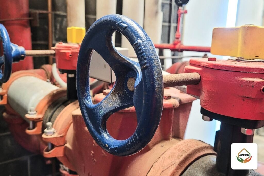
A sprinkler zone control valve assembly (also called a floor control valve assembly) is the small set of components fitted on the riser at each floor: a supervised control valve that isolates the floor, a waterflow switch that sends the alarm, a pressure gauge, a test and drain valve and a check valve. It tells the fire alarm panel which floor is flowing water, and it lets the maintenance team isolate and drain one floor without shutting down the whole building. This guide explains each component, how the assembly connects to the fire alarm system and what the consultant checks in the submittal, using valves and switches listed on AZEIDK’s fire fighting systems pages.
Key takeaways
- A typical assembly has a supervised control valve, a check valve, a drain and test valve, a waterflow switch and a pressure gauge.
- The Los Angeles Department of Building and Safety plan check list for NFPA 13 (2022 edition) calls for floor control valves at each floor, located on the floor they serve (Section 16.9.10.1).
- The valve and the flow switch are electrically supervised by the fire alarm panel, each with its own signal: supervisory for the valve, alarm for the flow.
- The test outlet simulates the flow of one sprinkler, so the technician can prove the flow switch alarms at that flow.
- The approved design and the code edition on the building permit decide how many assemblies are needed and where.
In this article
- What is a sprinkler zone control valve and why is one fitted on each floor?
- Sprinkler zone control valve components: what sits on each floor?
- Component table and what the consultant checks
- How does the zone control valve connect to the fire alarm system?
- Common installation mistakes
- Testing at handover and during maintenance
- Frequently asked questions
- Conclusion
What is a sprinkler zone control valve and why is one fitted on each floor?
In a multistory building the riser rises from the pump room or the main alarm valve and branches at each floor into that floor’s sprinkler network. The zone control valve assembly sits at that branch point. Without it the building is one zone: any operating sprinkler gives a general alarm that does not identify the floor, and any modification or leak on one floor means shutting the whole system.
The assembly solves two problems. In an emergency, Civil Defense and the building team read on the panel that water is flowing on, say, the fifth floor and go straight there. During maintenance, one floor can be isolated and drained to replace a sprinkler or repair a pipe while the other floors stay protected.
The reference standards call for this arrangement. The LADBS plan check list based on NFPA 13 (2022) cites Section 16.9.10.1: provide floor control valves at each floor, and locate each valve on the floor it serves. A technical article in PHCP Pros notes that NFPA 13 requires these assemblies in buildings over two stories, with specific exceptions. The design engineer therefore decides whether assemblies are needed, and how many, from the edition on the permit and the Civil Defense requirements, not from a rule of thumb.
Sprinkler zone control valve components: what sits on each floor?
The assembly is rarely bought as one packaged unit. It is usually built from separate components on site or in the workshop. In order, from the riser toward the floor piping:
1. Supervised control valve
This valve isolates the floor network. It is normally open and of the indicating type, so anyone can see whether it is open or closed. Butterfly valves are common because they are compact; OS&Y gate valves are used for larger sizes or where the consultant asks for them.
Example from AZEIDK’s range: the American AFC BFG-300 and BFG-301 grooved butterfly valves. The product page lists sizes from 2 to 12 inches, 300 psi (21 bar) working pressure, UL listing and FM approval as shown in the catalogue, and a built-in supervisory switch that signals the fire alarm system if the valve moves from its required position. OS&Y valves use an external switch such as the Potter OSYSU.
2. Waterflow switch
Fitted downstream of the valve, it has a paddle inside the pipe that moves when water flows. When a sprinkler on the floor operates, the switch closes a contact that the monitoring module passes to the fire alarm panel. A retard timer prevents false alarms from short pressure surges.
Example: the Potter VSR waterflow switch. Its page lists an adjustable retard of 0 to 90 seconds, two SPDT contacts, UL listed models for 2 to 6 inch pipe (Schedule 5 to 40) and UL listed and FM approved models for 2 to 8 inch pipe (Schedule 10 to 40). The switch size follows the floor pipe diameter and schedule, so the schedule must appear in the submittal.
3. Pressure gauge
It reads the pressure in the floor pipe. Used with the drain, it helps reveal a partly closed valve or a leak. Example: the WIKA 111.10SP, with a 4 inch dial, 0 to 300 psi water range, UL 393 listing and FM approval, and a 1/4 inch NPT connection.
4. Test and drain valve
A three-position valve: closed, test (water passes through an orifice sized like a sprinkler to simulate one sprinkler operating) and full drain. Its outlet connects to a drain line, usually a vertical drain pipe next to the riser.
5. Check valve
PHCP Pros lists the check valve as part of the assembly, together with the control valve, the drain valve and the flow switch. It limits backflow movement that could lift the flow switch paddle and cause an unwanted alarm. Its type and size follow the approved design, and it does not replace a backflow preventer on the supply.
Component table and what the consultant checks
| Component | Function | Example available from AZEIDK | What the submittal must show |
|---|---|---|---|
| Supervised control valve | Isolates the floor and signals when operated | AFC BFG-300/301 with built-in supervisory switch | Size, working pressure, UL/FM, end type (grooved or flanged) |
| Waterflow switch | Sends an alarm when water flows | Potter VSR | Pipe size and schedule match, retard range, listing |
| Pressure gauge | Reads floor pressure | WIKA 111.10SP | Range, listing, connection size |
| Test and drain valve | Simulates one sprinkler and drains the floor | Selected per project | Test orifice versus smallest sprinkler, drain route |
| Check valve | Reduces alarms from reverse water movement | Selected per project | Size, listing, flow direction |
How does the zone control valve connect to the fire alarm system?
The assembly gives the panel two different signals, and they must never be mixed up:
- Alarm: from the flow switch. Water is flowing, so a sprinkler has operated or there is a major leak. It is programmed as a fire alarm and drives the notification devices according to the cause and effect matrix.
- Supervisory: from the valve switch. The valve has moved from fully open. It does not start evacuation, but it warns the building team that the floor may be unprotected.
In an addressable system each point connects through a switch monitor module with its own address, so the panel shows a clear label such as “Floor 3 flow” or “Floor 3 valve”. We cover the wiring and the Context Plus modules in switch monitor modules for flow switches and valves.
Fire codes based on the International Fire Code (IFC), such as the California Fire Code, state that valves controlling the sprinkler water supply and waterflow switches are electrically supervised by a listed fire alarm control unit, that alarm, supervisory and trouble signals are distinctly different, and that the waterflow alarm device operates at a flow equal to one sprinkler of the smallest orifice in the system. The Saudi Fire Code SBC 801 is based on the IFC, so check the matching clause in the edition on your permit before the drawings are approved.
Common installation mistakes
- Flow switch size or schedule does not match the pipe: the paddle does not move as intended, so the alarm is late or missing.
- Switch too close to an elbow or valve: turbulence causes false alarms. Follow the distances in the switch installation manual.
- Retard set to zero: a surge when the jockey pump starts can trigger an alarm.
- No proper drain outlet: test water ends up on the floor or somewhere that cannot take the flow.
- Floor valve installed outside the floor it serves: contrary to the NFPA 13 plan check item above, and confusing in an emergency.
- No labels: no sign on the assembly and no clear description on the panel, so time is lost finding the floor.
Testing at handover and during maintenance
At handover the technician opens the test valve on each floor and times the flow alarm at the panel, partly closes the floor valve to confirm the supervisory signal, and records the gauge reading. The floor is then drained, refilled and every signal is confirmed back to normal. These steps are part of our testing, commissioning and handover service.
After commissioning, testing of flow switches and valve switches belongs in the routine maintenance programme for fire, safety and alarm systems, covered by AZEIDK’s preventive and routine maintenance contracts.
Frequently asked questions
What is the difference between a zone control valve and the main alarm valve?
The alarm check valve is installed once at the system inlet on the main riser and serves the whole system. A zone control valve assembly is fitted on each floor and divides the system into zones. See AFC ACV-300 wet alarm check valve.
Does every building need a control valve on each floor?
No. It depends on the number of floors, floor area and system type, and NFPA 13 has exceptions. The design engineer decides based on the edition on the permit.
Is a chain and padlock enough instead of electrical supervision?
Standards allow more than one supervision method in some cases, but IFC-based fire codes require electrical supervision of valves controlling the sprinkler water supply. Follow the approved drawings.
What retard setting should the flow switch have?
On the Potter VSR, for example, the retard is adjustable from 0 to 90 seconds. The designer sets the value according to system pressure, surges and alarm requirements. Do not leave it at zero.
Why does the flow switch alarm when no sprinkler has operated?
Usual causes are pressure surges when the jockey pump starts, a retard set too short, a switch fitted near an elbow, or trapped air. A check valve in the assembly reduces this.
What documents belong in the assembly submittal?
Datasheets for each component, UL or FM certificates, a riser diagram showing each assembly and the drain route, and the wiring diagram to the fire alarm panel.
Conclusion
The zone control valve assembly is a small item on the drawing, but it decides how fast the fire floor is identified and how easily each floor can be maintained. Choose a supervised valve and a flow switch matched to the pipe size and schedule, add the gauge and the test and drain valve, and wire the two signals to the panel as alarm and supervisory. For the other valves on the network see our fire protection valves and network components guide, and for brand details see American Fire Control.
Preparing a riser for a multistory building? Send the riser diagram, the number of floors and pipe sizes, and our team will prepare the valve, flow switch and gauge schedule with datasheets and certificates. Talk to the AZEIDK team
Related guides
- Sprinkler Pipe Hanger Spacing and Supports Under NFPA 13
- Fire Hose Reel Guide: Lengths, Bores, Installation and Inspection in Saudi Arabia
- Factory and Warehouse Networks: Industrial Wi-Fi, Fiber Between Buildings and Network Rooms
- Commercial Kitchen Fire Suppression in Saudi Arabia: Components and Requirements