
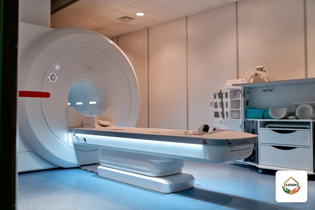
A non-magnetic fire sprinkler is a sprinkler made from materials that are not attracted by a magnetic field, installed in the ceiling of an MRI scanner room instead of a standard head. The reason is simple: the scanner’s static field pulls ferromagnetic objects with great force, so any ferrous component in the room is a hazard to patients, staff and the equipment. One model designed for this duty is the TYCO Series RFII-MRI (SIN TY3537).
This article is written for hospital engineers and MEP contractors fitting out an MRI suite. It covers what the official TFP262 datasheet says about this sprinkler, how sprinkler piping and hangers inside the RF shield are coordinated with the MRI vendor, and how to keep system impairments short. Full specifications are on AZEIDK’s TYCO RFII-MRI non-magnetic concealed pendent sprinkler (TY3537) product page.
Key takeaways
- The static field in an MRI room attracts magnetic objects. The U.S. FDA warns they can become projectiles that injure patients or staff or damage the scanner.
- The TYCO RFII-MRI (TY3537) is a concealed pendent, quick response, extended coverage light hazard sprinkler with a K-factor of 5.6, UL and C-UL Listed.
- Per datasheet TFP262, non-clinical testing to ASTM F2052-15 found it acceptable for use in a static magnetic field of 7 Tesla or less.
- It is mounted in the scanner room ceiling, near the scanner, and never inside the MR system or its bore.
- The head alone is not enough: piping, hangers and shield penetrations need early coordination with the MRI vendor and the RF shielding contractor.
In this article
- Why does an MRI room need a non-magnetic fire sprinkler?
- TYCO RFII-MRI specifications from datasheet TFP262
- Where should a non-magnetic sprinkler go, and where not?
- Coordinating sprinkler piping inside the RF shield with the MRI vendor
- How is the TYCO RFII-MRI installed?
- Managing sprinkler impairments during MRI room works
- Inspection and maintenance after handover
- TYCO non-magnetic sprinklers from AZEIDK
- Frequently asked questions
- Conclusion
Why does an MRI room need a non-magnetic fire sprinkler?
An MRI scanner operates with a strong static magnetic field. The FDA’s MRI benefits and risks page states that this field attracts magnetic objects, which may damage the scanner or injure patients or staff if they become projectiles, and that careful screening of people and objects entering the MR environment is critical.
A standard sprinkler may include parts whose behaviour in that field is not established. A non-magnetic sprinkler is made from non-ferrous materials and tested for magnetically induced displacement force. The test standard is ASTM F2052, Standard Test Method for Measurement of Magnetically Induced Displacement Force on Medical Devices in the Magnetic Resonance Environment. It measures the force that static field gradients exert on an object and compares it with the object’s weight. It does not cover torque or RF heating.
In practice, a sprinkler in an MRI room ceiling is part of the scanner environment. It must be selected against the manufacturer’s conditions for that environment, not against the rules used for ordinary hospital rooms.
TYCO RFII-MRI specifications from datasheet TFP262
The data below comes from the official Johnson Controls / TYCO datasheet TFP262 (August 2022), Series RFII-MRI, 5.6 K-factor Non-Magnetic Concealed Pendent Sprinklers, and from AZEIDK’s product page. You can download the TFP262 datasheet from our document library.
| Item | Value per TFP262 |
|---|---|
| Model and SIN | Series RFII-MRI, SIN TY3537 |
| Type | Concealed pendent, quick response, extended coverage light hazard (ECLH) |
| Approvals | UL and C-UL Listed, only for the service conditions in the Design Criteria section |
| K-factor | 5.6 GPM/psi½ (80.6 LPM/bar½) |
| Maximum working pressure | 175 psi (12.1 bar) |
| Temperature ratings | 155°F (68°C) sprinkler with 139°F (59°C) plate, or 200°F (93°C) sprinkler with 165°F (74°C) plate |
| Bulb | 3 mm glass bulb |
| Connection | 1/2 in. NPT |
| Vertical adjustment | 1/2 in. (12.7 mm) |
| Materials | Bronze frame and deflector; brass support cup, compression screw, cover plate and retainer; stainless steel guide pins and ejection spring; bronze or copper cap; beryllium nickel sealing assembly with PTFE |
| Magnetic compatibility | Acceptable in a static field of 7 Tesla or less, per non-clinical testing to ASTM F2052-15 |
Coverage and flow criteria
The datasheet gives three coverage areas, each with a minimum flow and pressure, to be used together with the current NFPA 13 requirements for extended coverage pendent sprinklers:
| Coverage area | Minimum flow | Minimum pressure |
|---|---|---|
| 16 × 16 ft (4.9 × 4.9 m) | 26 GPM (98.4 LPM) | 21.6 psi (1.49 bar) |
| 18 × 18 ft (5.5 × 5.5 m) | 33 GPM (124.9 LPM) | 34.7 psi (2.39 bar) |
| 20 × 20 ft (6.1 × 6.1 m) | 40 GPM (151.4 LPM) | 51 psi (3.52 bar) |
These values feed the system hydraulic calculation. The designer sets the room’s hazard classification and coverage area on the approved drawings. For concealed sprinklers and cover plates in general, see Concealed Sprinkler Head: Cover Plate, Temperature Ratings and Installation.
Where should a non-magnetic sprinkler go, and where not?
TFP262 states that the RFII-MRI is intended for use inside the MRI environment, meaning the MR system room close to the scanner, and must be mounted at the ceiling on the room’s fixed fire protection piping. It is not intended for use directly inside the MR system, such as within the bore of the scanner.
The datasheet adds a limit that matters in MRI rooms: do not use the sprinkler where the air pressure above the ceiling is greater than below it, because down drafts through the sprinkler can delay operation in a fire. Confirm the pressure relationship between the room and the ceiling void with the HVAC engineer before the model is approved.
Coordinating sprinkler piping inside the RF shield with the MRI vendor
An MRI room is usually enclosed by an RF shield that keeps interference away from the scanner. A 2017 Consulting-Specifying Engineer article on MEP/FP design for MRI suites states that all sprinkler system components in MRI rooms must be non-ferrous, commonly copper, brass and stainless steel, and that hangers and supports inside the RF shield must also be non-ferrous. It also notes that piping penetrations into RF-shielded areas pass through RF filters or waveguides and dielectric breaks, and that piping in adjacent spaces needs careful consideration.
Coordination points before shop drawings are approved
- Vendor requirements: obtain written requirements from the MRI vendor and RF shielding contractor for pipe and hanger materials and penetration locations.
- Pipe penetration: fix where the sprinkler line enters the room, the type of waveguide or dielectric break, and who supplies and installs it.
- Valves and flow switches: locate control valves, flow and supervisory switches outside the room, accessible without entering the scanner environment, as agreed between the designer and the hospital.
- Head locations: coordinate with the scanner position, HVAC and lighting, keeping heads in the ceiling and clear of the bore if the vendor requires it.
- System type: the designer and the hospital’s consultant decide the system type for the room within project requirements, and confirm the model is listed for that use.
Our guide to fire protection systems in Saudi hospitals covers the wider hospital picture. This article focuses on the MRI room only.
How is the TYCO RFII-MRI installed?
TFP262 sets out clear installation steps. The key ones:
- Install in the pendent position only, with the centreline perpendicular to the ceiling.
- Do not install a sprinkler with a cracked bulb or a bulb that has lost liquid.
- Tighten to 7–14 ft-lb (9.5–19.0 N·m) using only the RFII sprinkler wrench. Do not compensate for poor adjustment by over- or under-tightening; reposition the fitting instead.
- Refit the protective cap during ceiling work. Its tip can mark the centre of the ceiling hole.
- The ceiling clearance hole is 2-3/8 to 2-5/8 in. (60.3–66.7 mm); the cover plate is 3-1/4 in. (82.6 mm) in diameter with a 3/16 in. (4.8 mm) profile.
- Check that the deflector moves up and down freely before fitting the cover plate.
- A nominal 3/32 in. (2.4 mm) air gap between the cover plate and ceiling is needed for proper operation and must not be sealed by paint.
The sprinkler is listed only with TYCO Series RFII-MRI non-magnetic cover plates with a factory-applied finish. Do not substitute another cover plate and never paint it on site.
What to check in the submittal
- Model TY3537 and the part number for the required temperature (51-802-1-155 or 51-802-1-200).
- The matching cover plate for temperature and finish (Grey White RAL 9002, Signal White RAL 9003, Jet Black RAL 9005, brass or custom).
- The RFII sprinkler wrench (P/N 56-000-1-075).
- Hydraulic calculations for the selected coverage area.
- The MRI vendor’s written requirements for pipe and hanger materials.
Managing sprinkler impairments during MRI room works
TFP262 notes that the system is considered out of service while the protective cap remains in place. In an operating hospital, plan ceiling works so the caps come off and the cover plates go on as soon as the ceiling is finished.
The datasheet also requires that, before closing a main control valve for maintenance, permission to shut down the system is obtained from the proper authorities and all affected personnel are notified. NFPA 25 includes requirements for managing impairments, applied together with the manufacturer’s instructions and the requirements of the General Directorate of Civil Defense. Sensible measures for an MRI room include:
- Notify department management and the hospital’s safety team of the impairment period and area.
- Keep valve closures as short as possible, then restore the system and confirm the signal at the fire alarm panel.
- Keep ferrous tools and equipment out of the scanner room and follow the screening procedures applied by the radiology department.
Inspection and maintenance after handover
The datasheet requires inspection, testing and maintenance to NFPA 25 and the authority having jurisdiction. Model-specific instructions include:
- Replace any sprinkler that leaks, shows corrosion, or was dropped, struck or damaged by a slipping wrench.
- If a sprinkler must be removed, do not reinstall it or a replacement without reinstalling the cover plate/retainer assembly.
- If the ceiling is repainted, make sure paint has not sealed the air gap around the cover plate.
- Replace a dislodged cover plate immediately, because its absence can delay operation.
TYCO non-magnetic sprinklers from AZEIDK
AZEIDK supplies the TYCO RFII-MRI (TY3537) as part of its TYCO sprinkler range in Saudi Arabia and its solutions for hospitals and healthcare facilities. To compare other TYCO models used in hospitals, such as corridor sprinklers and concealed heads for architectural ceilings, see Selecting TYCO Sprinklers for Projects.
Frequently asked questions
Can a standard sprinkler be used in an MRI room?
It is not recommended. A sprinkler in an MRI room is part of the scanner environment, so use a model designed and tested for it, such as the TYCO RFII-MRI, under the manufacturer’s conditions and the MRI vendor’s requirements.
What field strength is the TY3537 rated for?
Per TFP262, non-clinical testing to ASTM F2052-15 found it acceptable in a static magnetic field of 7 Tesla or less.
Can a non-magnetic sprinkler be installed inside the MRI scanner?
No. It is mounted in the scanner room ceiling near the scanner, never inside the MR system or its bore.
Is the TYCO RFII-MRI FM Approved?
Datasheet TFP262 lists UL and C-UL Listing only, for the service conditions in its design criteria.
Can the cover plate be painted to match the ceiling?
No. The datasheet prohibits field painting of the sprinkler or cover plate. Order a factory finish from the standard colours or as a custom finish.
Conclusion
Choosing a non-magnetic fire sprinkler for an MRI room starts with the datasheet: model, listing, field strength limit and mounting location. Equally important is coordinating piping, hangers and shield penetrations with the MRI vendor and RF shielding contractor, and planning impairments in a live hospital. Resolving these points at drawing stage is far easier than changing them after the scanner is installed.
Fitting out an MRI room? Send us the room layout, the MRI vendor’s requirements and the temperature rating you need, and we will prepare the datasheet and submittal for the TYCO RFII-MRI. Contact the AZEIDK team
Related guides
- Salamah Certificate for Retail Shops: Steps from Lease to Issue and the Link with the Balady Licence
- Addressable Fire Alarm Panel Programming: Addresses, Zone Names, Delays, Lift and HVAC Interfaces, and Program File Handover
- Fire Drawings and Specifications Review Before Construction: A Checklist
- Fire Hose Types and Sizes: Rack, Reel, Lay-Flat, Couplings and Inspection