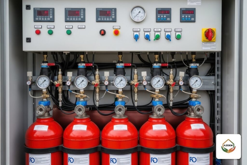



A fire pump anti vortex plate, an eccentric reducer, an automatic air release valve and a flow meter loop are small items compared with the pump, yet they decide whether water reaches the impeller steadily and free of air, and whether the pump can be tested accurately. This guide covers the accessories on the suction and discharge piping of a fire pump: what each one does, where it goes and what the consultant checks before handover on Saudi projects.
Key takeaways
- When the pump draws from a tank, an anti vortex plate at the tank outlet stops a vortex from pulling air into the suction pipe.
- Where the suction pipe is larger than the pump inlet, an eccentric tapered reducer is installed so that no air pocket can form.
- An automatic air release valve vents trapped air from a horizontal pump casing. It is not the same item as a pressure relief valve.
- On the discharge: a check valve, then a supervised control valve, with the test line branching between them.
- A flow meter loop saves water during tests, but needs an alternate means of measurement in series to confirm its accuracy.
In this article
- Why fire pump accessories matter as much as the pump
- Suction side and the fire pump anti vortex plate
- Fire pump air release valve vs pressure relief valve
- Discharge side: check valve, control valve and gauges
- Test header or flow meter loop?
- What the consultant checks before accepting the pump room
- Choosing a pump package with its accessories from AZEIDK
- FAQ
- Summary
Why fire pump accessories matter as much as the pump
A UL listed or FM approved pump only delivers its published curve if water enters it at an even velocity and without air. Air in the suction line causes pressure fluctuation, noise and impeller wear, and turbulence close to the inlet loads one side of a split case impeller more than the other. NFPA 20 therefore sets detailed rules for suction and discharge arrangements, and Saudi consultants normally ask for a pump room drawing showing these items as part of the submittal.
This article stays with the piping around the pump. Room layout, ventilation, drainage and separation are covered in our guide to fire pump rooms in Saudi Arabia, and the pumps AZEIDK supplies are listed in the fire pumps section.
Suction side and the fire pump anti vortex plate
The fire pump anti vortex plate
When a pump takes suction from a ground or elevated tank, the water level drops during a long run. At a certain depth the water starts to rotate above the suction inlet and forms a funnel that draws air into the pipe. An anti vortex plate is a flat metal plate fixed at a set distance above the suction inlet inside the tank. It breaks the rotation and lets the design use more of the tank volume without air entrainment.
Plate size and clearances are not decided on site. The designer sets them in line with the fire pump and water tank standards adopted for the project, and they belong on the tank shop drawing. Material and fixing matter too: inspecting the plate means draining the tank, so it should not corrode or work loose.
Suction control valve
The suction line carries an indicating outside screw and yoke (OS&Y) gate valve, supervised by a tamper switch connected to the fire alarm panel. As Consulting-Specifying Engineer explains, NFPA 20 does not allow any valve other than an OS&Y gate valve in the suction pipe within 50 ft (about 15 m) of the pump suction flange, because valves such as butterfly valves disturb the incoming flow. See our article on AFC OS&Y gate valves.
Eccentric reducer
The suction pipe is often larger than the pump inlet because it is sized for low velocity. The transition must be an eccentric tapered reducer, not a concentric one, because a concentric reducer leaves a high point where air collects. The eccentric reducer is fitted with its flat side on top. Consultants check this visually, and reducers installed upside down are a common site defect.
Velocity and elbows near the suction flange
According to the same Consulting-Specifying Engineer summary, the suction pipe is sized so that velocity within 10 pipe diameters of the suction flange does not exceed 15 ft/s (4.57 m/s) at 150% of rated capacity. For horizontal split case pumps, an elbow or tee whose plane is parallel to the pump shaft must be at least 10 pipe diameters from the suction flange, because it feeds the two sides of the impeller unevenly. No such limit applies when the plane is perpendicular to the shaft.
Fire pump air release valve vs pressure relief valve
The two are often confused in quotations. An automatic air release valve is float operated: it opens when air collects at the top of a horizontal pump casing, vents it and closes again when water reaches it. The US Unified Facilities Guide Specification UFGS 21 30 00 for fire pumps, which references NFPA 20 (2022), requires horizontal pumps to be equipped with automatic air release devices.
A pressure relief valve protects the system from overpressure, and a circulation relief valve passes a small flow to stop the pump overheating while running against a closed discharge. These are pressure devices, not air vents; see our article on Cla-Val fire pump valves.
In practice, ask the pump supplier to state on the datasheet or package drawing whether the air release valve is factory fitted, its size and where it drains, and check at handover that its drain has not been valved off.
Discharge side: check valve, control valve and gauges
The usual sequence after the discharge flange is a discharge pressure gauge, a check valve, then a supervised control valve that isolates the pump for maintenance. The check valve holds system pressure after the pump stops and prevents backflow from the system or the fire department connection into the pump; details are in our article on AFC swing check valves.
A compound gauge (reading positive and negative pressure) is fitted on the suction where the pump draws from a tank below its level, with a pressure gauge on the discharge. Together they give the net pressure recorded in tests. For gauges and pressure switches see fire sprinkler pressure gauges and fire pump pressure switches.
Where the supply has useful pressure, a bypass is installed around the pump. Consulting-Specifying Engineer notes that it is sized like the discharge pipe and carries a check valve with control valves on both sides for maintenance.
Test header or flow meter loop?
Every fire pump must be testable at rated flow and at 150% of rated flow. The two main arrangements compare as follows:
| Item | Test header | Flow meter loop |
|---|---|---|
| How it works | 2.5 in hose valves, flow measured with a pitot at each outlet | A meter on a line returning water to the tank or the suction pipe |
| Water use | Water is discharged out of the system | No water lost when returned to the tank |
| Where it branches | Between the discharge check valve and control valve | From the discharge, returning to the tank or suction |
| Accuracy check | Direct measurement at each outlet | Needs an alternate measuring means in series |
| Suits | Sites where test water can be discharged safely | Sites with limited water and frequent testing |
Consulting-Specifying Engineer places the test header connection between the discharge check valve and the discharge control valve, so the pump can be tested with the control valve closed, and gives the example of a 1,250 gpm pump needing six 2.5 in hose valves. The number of outlets follows the table in the standard for the pump’s rating.
Fire pump flow meter installation: three checks
- Listing and range: UFGS 21 30 00 calls for a UL listed or FM approved meter able to measure any flow between 50% and 150% of pump capacity.
- Alternate measurement: according to the First Revision report for the 2025 edition cycle of NFPA 20 (4.22.2.10.1), the alternate means of measuring flow shall be located downstream of and in series with the flowmeter, so the two readings can be compared.
- Air in the loop: where meter piping between pump discharge and suction forms an inverted U, UFGS 21 30 00 requires an automatic air release at the high point.
AZEIDK supplies GVI fire pump test meters. GVI’s brochure states FM approval, 0.5% accuracy and friction loss below 1 psi, and its operating procedure includes purging air from the meter before readings are taken. The test procedure itself is in fire pump flow testing to NFPA 25 with a GVI meter.
What the consultant checks before accepting the pump room
- Anti vortex plate installed in the tank as drawn, photographed before the tank is filled.
- Suction reducer is eccentric, flat side up.
- No butterfly valve on the suction near the pump; the OS&Y valve is supervised and open.
- No elbow parallel to a split case pump shaft within 10 pipe diameters of the suction flange.
- Air release valve fitted with an open drain; circulation and pressure relief valves where drawn.
- Test header or meter loop complete with valves and an alternate means of measurement.
- Datasheet and listing certificate for each item in the approval file.
The SASO Technical Regulation for Fire Control Materials and Equipment requires a certificate of conformity for fire pumps through the SABER platform, so prepare that file early with the purchase order.
Choosing a pump package with its accessories from AZEIDK
In Saudi Arabia AZEIDK supplies WATEX UL/FM fire pumps (end suction, split case and vertical turbine), 3PUMP fire pump packages (electric, diesel and jockey) and Jack Pump. When you request a quotation, send the required flow and pressure, the water source (tank or mains) and the pump room drawing, and state whether you need a test header, a flow meter or both, so the offer covers the full accessory set and not just the pump.
FAQ
What are the main fire pump suction and discharge connections?
Suction: anti vortex plate (for tank supplies), OS&Y valve, eccentric reducer and gauge. On the pump: air release and circulation relief valves. Discharge: check valve, control valve and gauge, then the test header or flow meter.
Is an anti vortex plate always required for a fire pump?
It is used where the pump takes suction from stored water in a tank. A pump fed from a pressurised main does not need one. Size and position follow the designer’s detail and the standards adopted for the project.
Why is the eccentric reducer installed flat side up?
So that no air pocket forms at the top of the pipe ahead of the pump inlet. A concentric reducer, or an eccentric one fitted upside down, traps air.
What is the difference between a fire pump air release valve and a relief valve?
The air release valve vents trapped air from the casing using a float. The relief valve opens above a set pressure to protect the system.
Can a flow meter replace the test header?
A meter loop can be used for testing, but an alternate means of measurement in series is needed to verify its accuracy, and some specifications, such as UFGS 21 30 00, call for both an exterior test header and a flow meter.
What does a vortex plate for fire pump suction cost?
It depends on the suction pipe size, material and how it is fixed in the tank, and it is usually priced with the tank or pump room works. Send the drawing and we will list the items.
Summary
Fire pump accessories are not extras. The anti vortex plate, eccentric reducer and air release valve keep air and turbulence out of the pump; the check valve, control valve and test header or flow meter make it possible to isolate and test it. Check each item on the drawings before installation and again on site before acceptance.
Planning a fire pump room? Send the flow, pressure, water source and drawings, and our team will define the pump and its suction, discharge and test accessories. Contact AZEIDK
Related guides
- Fire Safety Log Book and Maintenance Records for Civil Defense Inspection and Salamah Renewal
- Visitor Management Systems for Companies and Compounds: Pre-Registration, Badge Printing and Integration with Gates and CCTV
- CCTV Supply and Installation Contract Template: Clauses to Include
- Business Wi-Fi Network Design: How to Size Access Points, Placement, PoE Switches and Central Management