
ELV shop drawings are the detailed installation drawings that technicians use to fix every camera, data outlet and access control device on site. They show where each device goes, how each cable is routed, which power points are needed and where every rack sits. They start from the consultant’s design drawings and specifications, then get coordinated with the electrical, HVAC, ceiling and interior drawings before submission for approval. This article explains what a complete ELV shop drawing package contains for each system, how coordination works, and the most common reasons consultants reject these drawings on Saudi projects, as part of AZEIDK low current systems.
Key takeaways
- The design drawing says what to install. The shop drawing says exactly where, at what height and along which cable route.
- A complete ELV shop drawing package includes device layouts per system, riser diagrams, containment routes, rack elevations, and cable schedules with labeling.
- A CCTV shop drawing shows each camera’s field of view and target distance, not just its position.
- Most consultant comments come from clashes with lights, sprinklers and air diffusers in the ceiling, and from missing power points.
- As-built drawings are updated from the approved shop drawings after installation, so accurate shop drawings save time at handover.
In this article
- What are ELV shop drawings?
- What goes into an ELV shop drawing package?
- How is a CCTV shop drawing prepared?
- What do network and cabling shop drawings show?
- How are access control shop drawings drawn?
- How is electrical coordination handled?
- Why is ceiling and interior coordination the hardest stage?
- What are the steps to prepare and approve ELV shop drawings?
- What are the most common reasons ELV shop drawings get rejected?
- Frequently asked questions
- Conclusion
What are ELV shop drawings?
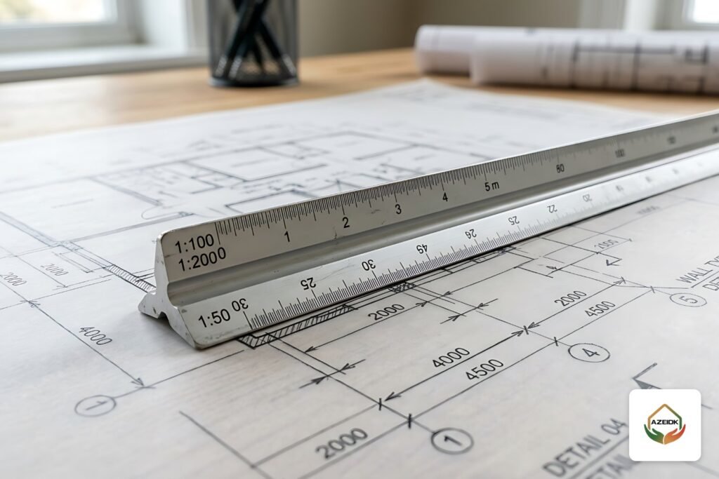
On most projects the contractor receives design or tender drawings from the consultant. They show the systems, approximate quantities and general device locations. They are not enough to install from, because they do not account for the real ceiling, the routes of other trades or the room sizes after finishing.
That is the job of the shop drawing. The ELV contractor prepares it after selecting the actual equipment and getting the datasheets approved. It fixes the real model and dimensioned location of each device, the cable type, length and route, and the racks and their contents. Once approved by the consultant, it becomes the single reference for the site team, and any later change needs a new review.
On Saudi projects, low current (ELV) usually covers CCTV, data networks and cabling, access control, intercom, public address, intrusion alarm and IP telephony. This article focuses on the three that appear most in approval packages: CCTV, networks and access control.
What goes into an ELV shop drawing package?
The package varies with project size and consultant requirements, but a complete one usually includes:
| Package item | What it shows | What the consultant checks |
|---|---|---|
| Legend and general notes | Symbol for each device, cable types, standard mounting heights | Symbols match the specification, no symbol used for two devices |
| Device layouts per floor and per system | Dimensioned location of every camera, data outlet and card reader | Coverage, quantities against the BOQ, clashes with other systems |
| Riser diagram | Links between floors, telecom rooms and the main equipment room | Logical distribution, switch and recorder capacity |
| Containment routes | Cable tray and conduit routes and sizes | No clash with ductwork, fire protection piping or power |
| Rack elevations and telecom room layout | Arrangement of switches, patch panels and recorders in each rack | Spare space, ventilation, power source and earthing |
| Installation details | How cameras, readers and locks are fixed, and at what height | Detail suits the wall or ceiling type |
| Cable schedule and labeling | Number, start point, end point and type of every cable | A clear labeling scheme that can be traced after handover |
How is a CCTV shop drawing prepared?
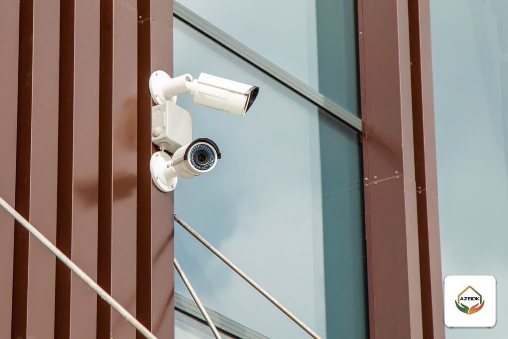
A common mistake is to show each camera as a dot on the plan. The consultant wants to see what each camera will cover, so the field of view is drawn for every camera, along with the distance at which it must deliver the required level of detail.
Level of detail is measured as pixel density on the target. IEC 62676-4, the application guideline for video surveillance systems, gives reference values known as DORI: detection at 25 px/m, observation at about 63 px/m, recognition at 125 px/m and identification at 250 px/m. Entrances and cash points usually need identification, while car parks and fence lines often need only observation. See our article on CCTV coverage for more.
The CCTV shop drawing should also show:
- Mounting height and bracket type (wall, ceiling or pole).
- The PoE switch feeding each camera, with the power budget checked as explained in PoE switch power budget for CCTV.
- The NVR location and the storage needed for the retention period, per NVR storage and bandwidth calculation.
- The regulatory requirements for camera locations in facilities, covered in the Saudi security surveillance cameras law.
What do network and cabling shop drawings show?
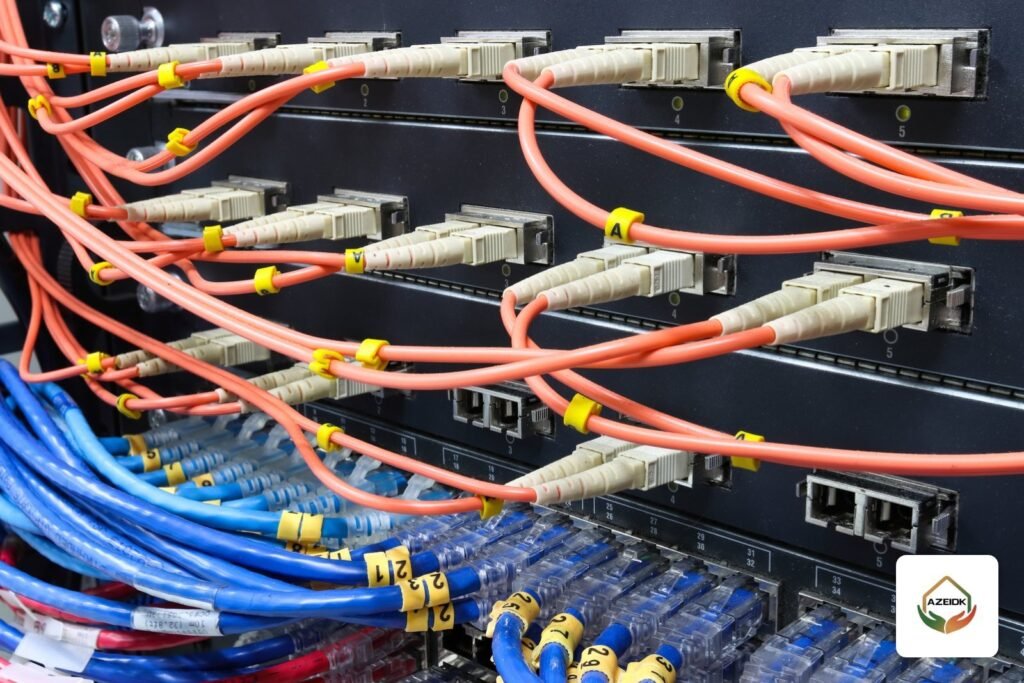
The network drawing is the backbone of the other ELV systems. On most projects today, cameras, access control, intercom and telephones all run on the same network, so engineers usually start here.
The drawing shows the floor telecom rooms (IDF), the main equipment room (MDF) and the pathways between them. ANSI/TIA-569-E, Telecommunications Pathways and Spaces (published May 2019), is the usual reference for planning these rooms and routes. For twisted-pair copper, the TIA-568 series limits the fixed horizontal link to 90 m and the full channel to 100 m, so the route length from each room to its farthest outlet is checked before the room location is fixed.
The package also includes a labeling schedule for every outlet, cable and patch panel. Many consultants ask for labeling to follow TIA-606, the administration standard for telecommunications infrastructure. Good labeling saves hours of maintenance later. For equipment, see network and communication systems.
How are access control shop drawings drawn?
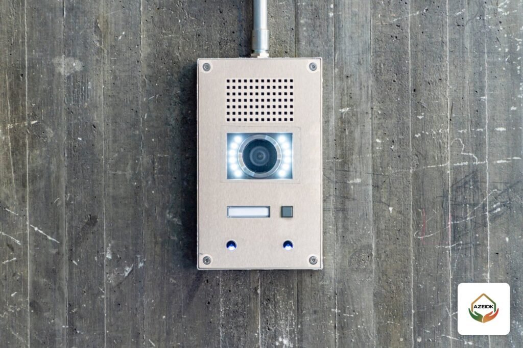
The access control drawing is built on the door schedule. For each door it defines the reader type (card, fingerprint or face), the lock type (magnetic or electric), the exit button, the door position contact, an emergency break glass unit where the consultant asks for one, and the controller it connects to.
Networked controllers such as ZKTeco InBio and C3 each handle a fixed number of doors depending on the model, so the engineer places them close to groups of doors, each with a power point and a backup power supply.
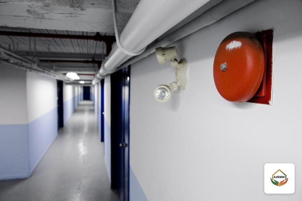
Consultants often focus on how the locks interface with the fire alarm system. Lock release on alarm is defined in the project cause and effect matrix, and the drawing must show where the interface module between the fire alarm panel and the door system sits. See fire alarm cause and effect matrix.
How is electrical coordination handled?
Almost every ELV device needs power: network racks, access controllers, locks, recorders and any camera not powered over PoE. A schedule of required power points, with their load and location, goes with the shop drawing and is sent to the electrical contractor before walls are closed.
Electrical coordination also covers:
- Which loads need UPS or emergency generator supply.
- An earthing point for every rack and telecom room.
- Separation between ELV and power cables in trays and conduits, as defined in the project specification.
- A clear agreement on who installs shared containment and who pulls each cable.
Where MEP works are delivered as one integrated package, this coordination happens in the combined services drawing, which is the best way to catch clashes early. See MEP works.
Why is ceiling and interior coordination the hardest stage?
In hotels, offices and malls the false ceiling is crowded: lights, sprinklers, smoke detectors, air diffusers, speakers, wireless access points and cameras. ELV device positions are transferred to the interior designer’s reflected ceiling plan and adjusted to sit correctly in the tile grid without losing coverage.
The interior review also covers the wall finish where readers or intercom panels are mounted, mounting heights, and access panels in closed gypsum ceilings. Many cameras get moved at the end of a project because the interior designer never saw them on the drawings. That rework can be avoided from day one.
What are the steps to prepare and approve ELV shop drawings?
- Review the design drawings, specification and BOQ, and log any gap or clash as an RFI.
- Get datasheets approved for the actual equipment, since device size and field of view affect the drawing.
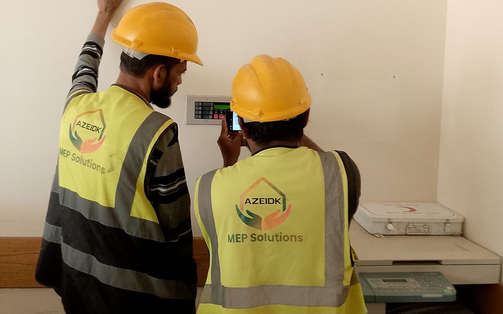
- Visit the site to confirm real heights and dimensions.
- Draw the layouts, riser, containment routes and racks.
- Coordinate with electrical, HVAC, fire protection and interior, and move any clashing devices.
- Check internally, submit to the consultant, and answer comments in a revised issue with a new revision number.
- After installation, update the drawings to as-built as part of documentation and final handover.
Approval codes (approved, approved as noted, rejected) differ between consultants, so read every comment before starting installation. For AZEIDK’s drawings and coordination service, see shop drawings and coordination.
What are the most common reasons ELV shop drawings get rejected?
- Device quantities do not match the BOQ or specification, with no explanation.
- Cameras shown without a field of view, so coverage cannot be assessed.
- No riser diagram or cable schedule.
- Devices clashing with lights, sprinklers or air diffusers.
- Power points and backup supplies not shown.
- Copper cable routes longer than the permitted length.
- Door interface with the fire alarm system not shown.
Frequently asked questions
What is the difference between ELV design drawings and shop drawings?
Design drawings define the systems, quantities and general locations. Shop drawings fix the actual model, the dimensioned position of each device and every cable route, and they are what technicians install from.
Who prepares ELV shop drawings?
Usually the ELV contractor, after the equipment is approved. The consultant then reviews and approves them before installation starts.
What should a CCTV shop drawing include?
Each camera’s position, height and field of view, the distance for the required level of detail, the switch feeding it and the recorder location.
Do shop drawings need to show cable routes?
On most projects, yes. Consultants ask for tray and conduit routes and sizes to confirm they do not clash with other systems.
When are ELV as-built drawings prepared?
After installation and testing. They are updated from the approved shop drawings with every site change, then handed to the owner.
Can CCTV, network and access control drawings go in one submittal?
Yes, if the consultant accepts it, as long as each system has its own layouts and schedules inside the package. Some consultants ask for a separate submittal per system.
Conclusion
Good ELV shop drawings are not measured by page count. They are measured by whether a technician can install from them without questions, and by how few changes happen on site. Start from approved equipment and the network drawing, draw camera fields of view and the door schedule, coordinate with electrical and interior before submission, and keep the drawings current until handover.
Need shop drawings for CCTV, networks and access control? The AZEIDK team supports design, supply, installation and coordination with other trades. Talk to the AZEIDK team
For a site survey or quotation, see CCTV supply and installation.
Related guides
- False Waterflow Alarm Sprinkler Fixes: Alarm Valve Retard and Potter VSR Timer
- Fire Blanket: When to Use It, Where to Mount It in Kitchens and Facilities, and How It Differs From an Extinguisher
- Approved Electrical Contractor for Commercial Projects in Saudi Arabia: Scope, SBC 401 and Electrical Works Within an Integrated MEP Package
- Time Attendance Devices: Choosing Fingerprint, Face or Card with ZKTeco and Hikvision Models