

Fuel storage tank fire protection relies mainly on low-expansion foam. On fixed-roof tanks the foam is delivered to the product surface through foam chambers; on floating-roof tanks foam pourers discharge it into the rim seal area. The technical reference for these systems is NFPA 11, and the edition cited in current NFPA references is 2024. This article explains how to choose the discharge method by tank and product type, what the system includes, and what goes into the design file, with links to what AZEIDK supplies for industrial facilities.
Key takeaways
- The tank roof type comes first: fixed roof or floating roof.
- Foam chambers are Type II discharge devices under NFPA 11, mounted on the tank shell above the maximum product level.
- Floating-roof tanks are usually protected at the rim seal with foam pourers.
- The application rate depends on the concentrate and the liquid, and cannot go below the device’s listed value.
- The proportioning side (bladder tank and ratio controller) and the concentrate must be listed with the discharge devices.
In this article
- Why does fuel storage tank fire protection need foam?
- What are the foam discharge methods for fuel tanks?
- How do foam chambers work on fixed-roof tanks?
- What do foam pourers do on floating-roof tanks?
- What does a fixed foam system for fuel tanks include?
- What goes into the design file for fuel tank protection?
- Common mistakes in fuel tank foam protection
- Frequently asked questions
- Conclusion
Why does fuel storage tank fire protection need foam?
A tank fire is a surface fire on a flammable liquid. Water alone will not put it out: it is heavier than most petroleum products, sinks below the surface, and can cause frothing with hot liquids. Foam floats on the liquid, forms a blanket that separates vapours from air, and cools the surface. That is why the standards rely on it for flammable liquid tanks.
In Saudi Arabia the system is designed to a technical reference adopted by the consultant, here NFPA 11, Standard for Low-, Medium-, and High-Expansion Foam, then approved by Civil Defense and the authority responsible for the industrial facility. Submission goes through the Salamah platform as part of Civil Defense approval support.
What are the foam discharge methods for fuel tanks?
Tank shape, roof type and product decide how foam reaches the surface. The table summarises the three most common methods as manufacturers describe them:
| Method | Tank type | How it works |
|---|---|---|
| Foam chambers | Fixed (cone) roof tanks | Mounted on the shell above the maximum product level; foam is directed onto the inner wall and runs gently onto the surface |
| Foam pourers | Floating-roof tanks | Discharge foam into the annular rim seal area between the floating roof and the shell |
| Subsurface injection | Closed-roof tanks | A high back-pressure foam maker injects foam near the tank bottom and it rises to the surface |
The choice is not a preference. It depends on what NFPA 11 permits for each tank and liquid, and on the listing of the discharge device. The study starts with a tank data schedule: diameter, height, roof type, product, flash point, and whether the product is water-miscible.
How do foam chambers work on fixed-roof tanks?
A foam chamber draws in air, mixes it with foam solution from the proportioning system, and pushes the expanded foam into the tank. Viking’s technical data for its foam chambers (November 2024) describes them as low-expansion Type II discharge devices as defined by NFPA 11, generally installed on the side wall of vertical tanks above the maximum storage level.
The chamber has a vapor seal that keeps tank vapours out of the foam line in normal service and bursts when solution pressure arrives; Viking gives a burst pressure of 10 to 25 psi. Inside the tank, a deflector directs the foam back onto the shell so it runs down gently. The number of chambers per tank increases with tank diameter according to NFPA 11 tables, so it is not a guess.
The key design figure is the application rate. The same Viking data gives different minimum densities by concentrate and liquid, including 0.10 gpm/ft² for a 3% synthetic concentrate on hydrocarbons, 0.20 gpm/ft² for a 3% alcohol-resistant concentrate on heptane and 0.25 gpm/ft² for the same concentrate on isopropyl alcohol, and states these values cannot be reduced. In practice, take the figure from the listed datasheet for the device with the chosen concentrate and from NFPA 11, and use the higher one.
What do foam pourers do on floating-roof tanks?
On a floating-roof tank the roof rides on the product, so there is little vapour space. Most fires start in the annular rim seal between the roof edge and the shell. Foam pourers are mounted at the top of the shell to pour foam into that ring, and ANSUL’s tank protection page lists rim seal foam pourers for floating-roof tanks among its products.
A foam dam on the floating roof is usually used with the pourers to keep foam in the ring. Dam dimensions, pourer spacing, application rate and discharge time all come from NFPA 11 and the datasheet, and feed into the system hydraulic calculations.
What does a fixed foam system for fuel tanks include?
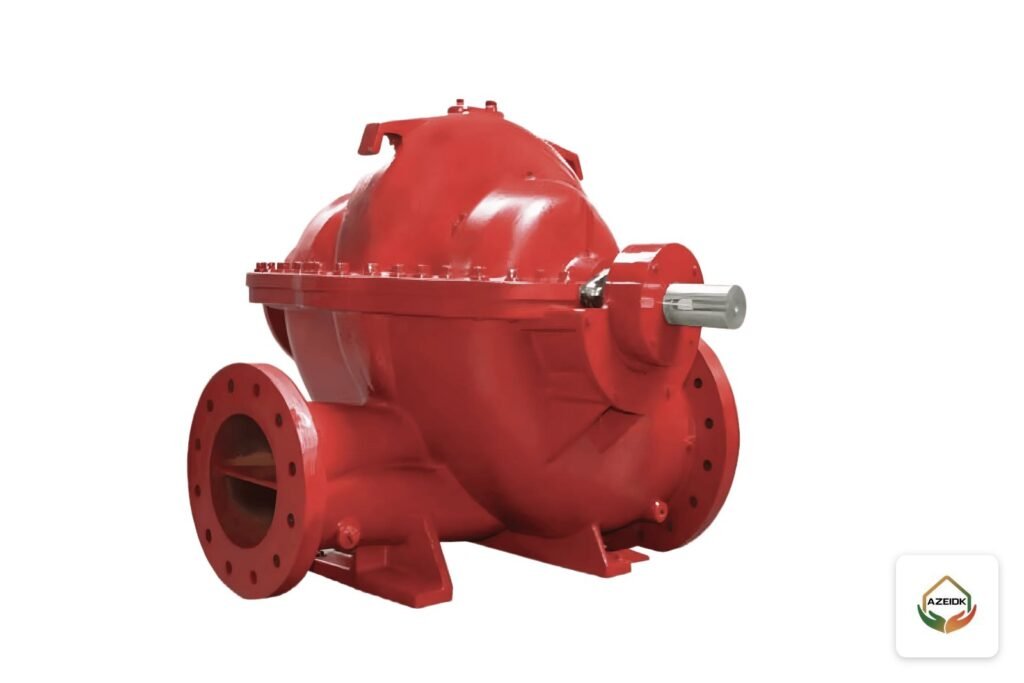
- Water supply and fire pumps: sized on the largest tank plus any supplementary protection running at the same time. See AZEIDK fire pumps.
- Bladder tank and ratio controller: mix concentrate with water at a fixed ratio without a foam pump. Options include the WATEX UL foam bladder tank, UL listed under certificate EX29807 to UL 162 with a 175 psi rating, and the SFFECO foam bladder tank with the SFFECO ratio controller.
- Foam concentrate: for example Safe Guard 3% AFFF. Water-miscible products such as alcohols need an alcohol-resistant concentrate, which changes the rate as the Viking figures show.
- Discharge devices: foam chambers, pourers or a subsurface foam maker, depending on the tank.
- Supplementary protection: foam monitors around the bund and at loading areas. The SFFECO foam monitors page lists tank farms and fuel depots among applications, with flows up to 50,000 L/min and manual or automatic operation.
- Detection and release: automatic systems are tied to detection. The SFP-IR3-EXD flame detector is explosion-proof to Ex db IIC T6 Gb, and its page lists fuel facilities and oil and petrochemical installations.
What goes into the design file for fuel tank protection?
| Item | What the file should show |
|---|---|
| Tank data | Diameter, height, roof type, product, flash point, water miscibility |
| Design basis | Adopted NFPA 11 edition, rate and discharge time per tank, and the governing tank |
| Concentrate quantity | Calculated from rate, time and proportioning ratio, plus supplementary protection |
| Hydraulic calculations | Solution pressure at each chamber or pourer within the datasheet range |
| Equipment approvals | UL or FM listing of discharge devices and proportioner with the chosen concentrate |
This file is prepared under engineering design and calculations. Check concentrate compatibility with every device before purchase, because changing the concentrate later can change rates and storage quantities.
Common mistakes in fuel tank foam protection
- Using a generic application rate without checking the device datasheet for the chosen concentrate.
- Using standard AFFF on water-miscible products.
- Mounting foam chambers below the tank’s maximum operating level.
- Ignoring supplementary protection for the bund and loading areas.
- No commissioning test and no periodic concentrate checks under preventive maintenance.
Frequently asked questions
What is a foam chamber?
A device mounted on the shell of a fixed-roof tank that mixes foam solution with air and discharges foam into the tank so it runs onto the product surface. NFPA 11 classes it as a Type II discharge device.
Foam chamber or foam pourer: what is the difference?
A foam chamber covers the full product surface in a fixed-roof tank. A foam pourer covers the rim seal ring of a floating-roof tank.
What is NFPA 11?
The NFPA standard for low-, medium- and high-expansion foam. The edition cited in current NFPA references is 2024.
What foam application rate does a fuel tank need?
It depends on the product, concentrate and device. Viking data, for example, gives 0.10 gpm/ft² for a 3% concentrate on hydrocarbons and higher values for alcohols. The final value comes from NFPA 11 and the datasheet.
Is tank foam enough without bund protection?
Usually not. Spills in the bund and loading areas need supplementary protection such as foam monitors, per the approved design basis.
Does subsurface injection suit every tank?
No. It is used on closed-roof tanks with a high back-pressure foam maker, and its use depends on the product and what NFPA 11 permits.
Conclusion
Fuel storage tank fire protection starts with roof type and product: foam chambers for fixed roofs, rim seal pourers for floating roofs, and subsurface injection where the standard allows it. Then come three linked decisions: the concentrate, the listed application rate for the device, and proportioning equipment listed with both.
Planning protection for fuel tanks or a tank farm? AZEIDK can support design and supply of foam bladder tanks, ratio controllers, foam concentrates and monitors. Talk to the AZEIDK team
Related guides
- CCTV Maintenance SLA: Response Time, Repair Time and Recording Availability
- WATEX UL-Listed Foam Bladder Tanks: Capacities, Specifications, Ratio Controllers and Sizing
- Voice Evacuation in Makkah Hotels and Pilgrim Housing: Multilingual Messages and Peak Crowds
- NEOM Supplier Registration, Aramco and SABIC: Documents Fire and Security Suppliers Need