
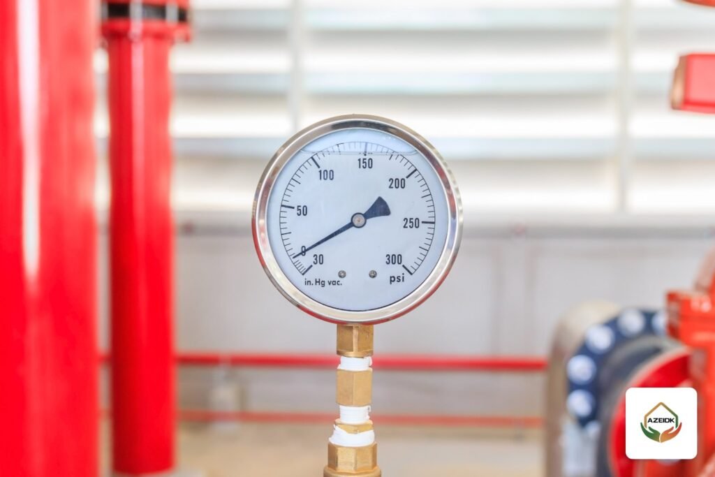
The pressure sensing line fire pump controllers rely on is the small pipe that carries discharge pressure to the pressure switch or transducer inside the controller, and the controller decides when to start based on what it reads. A leak, a blockage or trapped air in this line, or a badly set pressure relief valve, shows up on site as a pump that keeps starting and stopping or a pressure reading that will not settle. The fix starts with a methodical check of the line and the valves, not with changing the controller settings.
This article is written for maintenance technicians and facility engineers in Saudi Arabia dealing with a fire pump that cycles for no clear reason or a gauge that keeps moving. It complements our article on fire pump faults and troubleshooting and focuses on the sensing line and the relief valve. The pump ranges AZEIDK supplies are in the fire pumps category, part of AZEIDK fire fighting systems.
Key takeaways
- The sensing line connects to the discharge between the discharge check valve and the discharge control valve, as plan review checklists based on NFPA 20 require.
- Each controller has its own sensing line, including the jockey pump controller. Two pumps never share one line.
- A pressure relief valve is not fitted to every pump. It is installed where NFPA 20 calls for it, for example with variable speed pressure limiting control or a pressure limiting diesel driver when maximum pressure exceeds the rating of system components.
- The circulation relief valve is a different device. It protects the pump from overheating while it runs at churn.
- Frequent cycling is usually caused by a system leak or jockey settings, not by a fault in the main pump itself.
In this article
- Pressure sensing line fire pump basics: what does the line do?
- Sensing line requirements: material, size and separate lines
- Fire pump pressure relief valve: when is it required?
- Why a fire pump short-cycles and why the pressure reading fluctuates
- What the technician checks on the sensing line, step by step
- Common site mistakes
- Frequently asked questions
- Summary
Pressure sensing line fire pump basics: what does the line do?
The fire pump controller only sees the system through this line. When system pressure drops because a sprinkler opens or a hose cabinet is used, pressure in the sensing line drops too. The pressure switch or pressure transducer reads the drop, and the controller starts the pump at its set start pressure.
Where the line connects matters. The fire pump plan review checklist used by the City of Mobile Fire Department in the US, which is based on NFPA 20, requires the sensing line to be located between the pump discharge check valve and the discharge control valve. If the line is connected downstream of the control valve, closing that valve for maintenance cuts the controller off from the real system pressure.
Sensing line requirements: material, size and separate lines
The details come from the NFPA 20 edition adopted for the project and from the controller and pump manufacturer’s instructions. According to the NFPA 20 text quoted by Industrial Monitor Direct:
- Material: brass, rigid copper pipe Types K, L or M, or Series 300 stainless steel pipe or tube (2010 edition, Section 4.30.3).
- Size: fittings of ½ in. (15 mm) nominal size.
- No soft copper: Annex A of the same edition explains that soft copper tubing is not permitted because it is easily damaged.
- One line per controller: in all pump installations, including jockey pumps, each controller has its own individual sensing line. The wording has carried through later editions under new section numbers.
These are quotations from a secondary source, so check the text of the edition adopted for your project before relying on them in a submittal or inspection report.
Why are there small orifices in the sensing line?
A damping element is normally fitted in the sensing line so that fast pressure pulses do not reach the pressure switch directly and start or stop the pump with every surge. One example is the orifice union. The FPPI Fig. 08-539 datasheet lists a ½ in. brass union with a 3/32 in. orifice and states that it may only be used where the water is clear and sediment will not block the hole. That small orifice is also the weak point when the system water carries debris.
Fire pump pressure relief valve: when is it required?
A pressure relief valve opens and discharges water when discharge pressure rises above a set limit, protecting system components. It is not a standard item on every pump. According to the NFPA report from the revision cycle of the 2019 edition of NFPA 20 (Section 4.20.1.3):
- A pressure relief valve is installed where a variable speed pressure limiting control or a pressure limiting diesel driver is used and the maximum pressure exceeds the pressure rating of system components.
- In that case it is set at least 10 psi (0.68 bar) above the set pressure of the variable speed pressure limiting control.
The City of Mobile checklist also asks for a listed valve, either spring loaded or pilot-diaphragm type, with its listing datasheet submitted, and for the discharge pipe to be sized from the NFPA 20 table, enlarged by one pipe size if it has more than one elbow.
Relief valves supplied by AZEIDK include the Cla-Val 50B-4KG1 fire pump pressure relief valve, together with the Cla-Val WC-1 waste cone that lets the discharge be seen. Model and size are selected from the pump data and the datasheet. Our article on Cla-Val fire pump valves covers these valves in detail.
The circulation relief valve is not the pressure relief valve
When a pump runs with no flow, the water inside the casing heats up. The City of Mobile checklist, referring to NFPA 20, therefore requires an automatic relief valve on the discharge side before the discharge check valve, discharging to drain. For variable speed control, the same NFPA report says this valve is set at least 5 psi (0.34 bar) below the operating set pressure. The two valves are often confused on site, and each one is checked differently.
Why a fire pump short-cycles and why the pressure reading fluctuates
The table lists the common causes a technician checks, from the easiest to the hardest. It does not replace the controller and pump manufacturer’s manuals.
| Symptom | Likely cause | What the technician checks |
|---|---|---|
| Main pump starts before or with the jockey pump | Start and stop settings too close or reversed | Compare both controllers against the approved setting schedule |
| Jockey pump runs every few minutes | System leak or a drain valve not sealing | Drain and test valves, grooved couplings, hose cabinets |
| Pressure falls right after the pump stops | Discharge check valve not seating | Pressure on both sides of the valve, clapper and seat |
| Controller reading lags or does not change | Damping orifice or line blocked by debris | Remove and clean the orifice, compare the controller with the discharge gauge |
| Reading jumps up and down | Trapped air or pressure surges | Bleed air at the test connection, check the damping element |
| Pump does not start although system pressure has dropped | Closed valve in the sensing line, or line connected after the control valve | Trace the line from its connection point to the controller |
| Relief valve discharging continuously | Relief setting too close to operating pressure, or a pilot fault | Compare the setting with the design value, check the valve manual |
| Reading makes no sense although the line is sound | Faulty pressure switch or transducer | Compare with a calibrated gauge, then recalibrate or replace |
Start and stop pressure settings for the jockey, main and standby pumps are covered in detail in jockey pump sizing and pressure settings, so we do not repeat them here.
What the technician checks on the sensing line, step by step
These steps are general good practice for maintenance visits. Adapt them to the manufacturer’s instructions and site procedures:
- Notify and secure: tell building management the pump may start during the check and make sure the pump room is safe.
- Trace the line: from the connection on the discharge to the controller. Confirm the connection is between the check valve and the control valve and that no other controller shares it.
- Material and condition: no soft tubing or flexible hose substitutes, no dents, no leaks at fittings.
- Damping element: remove and clean the orifice union or orifice check valve, especially where the water carries sediment.
- Air: open the test connection slowly until water runs without bubbles.
- Compare readings: compare the controller reading with the discharge gauge. A clear difference points to the sensor or its calibration.
- Simulate a start: drop pressure gradually at the test connection, record the pressure at which the pump starts and compare it with the approved setting.
- Controller log: many modern controllers record events and pressure, including the minimum run timer. Review the log for the number and timing of starts.
Weekly and monthly checks for electric pumps are in our electric fire pump maintenance checklist, and pump room arrangement in the fire pump room checklist.
Common site mistakes
- Raising the start pressure or lowering the stop pressure to stop the cycling, instead of finding the leak.
- Fitting a shutoff valve in the sensing line and leaving it closed after maintenance.
- Running the jockey and main pump controllers off one line to save pipe.
- Replacing part of the line with a flexible hose or soft copper tube.
- Treating constant relief valve discharge as normal without reviewing the setting.
- Replacing the pressure switch with a model not named in the controller manual.
For the standard itself, see our NFPA 20 fire pump standard guide. In Saudi Arabia the Saudi Fire Protection Code SBC 801 and the requirements of the General Directorate of Civil Defense remain the binding framework, and NFPA 20 is used as the technical reference in design and specifications.
Frequently asked questions
What is a pressure sensing line on a fire pump?
It is the pipe that carries discharge pressure to the pressure switch or transducer in the controller, so the pump starts when pressure falls to the set value.
Where does the pressure sensing line connect?
Between the discharge check valve and the discharge control valve, so the reading stays correct when the control valve is closed.
Can the jockey pump and the main pump share one sensing line?
No. Each controller has its own sensing line, including the jockey pump controller.
Does every fire pump need a pressure relief valve?
No. It is installed where NFPA 20 calls for it, such as variable speed control or a pressure limiting diesel driver when maximum pressure exceeds the rating of system components. The designer decides this from the pump and system data.
Why does my fire pump keep starting and stopping?
The most common causes are a system leak, jockey and main pump settings that are too close, a check valve that does not seat, or a blocked sensing line.
What is the difference between a pressure relief valve and a circulation relief valve?
The first protects the system from overpressure. The second discharges a small flow while the pump runs at churn so the water inside does not overheat.
Summary
The pressure sensing line is the controller’s view of the system. Connecting it in the right place, in rigid material, with a separate line for each controller and a clean damping element, prevents most short-cycling and unstable readings. A pressure relief valve is fitted where the standard requires it and set to the design, and it should never be used to hide a pressure problem in the system.
Is your fire pump short-cycling or is the pressure reading unstable? The AZEIDK team checks the sensing line, valves and controller settings under corrective maintenance and technical support or annual maintenance contracts. Talk to the AZEIDK team
Related guides
- Safety and Security Tools for Facilities and Shops in Saudi Arabia: The Essential List and When Each Is Required
- Network Switch and Wi-Fi Brands in Saudi Arabia: Cisco, Huawei, Ruijie, TP-Link, Alcatel and UTEPO Compared
- Saudi Civil Defense Requirements for Buildings and Facilities
- SIP Trunk in Saudi Arabia: Connecting Your IP PBX to stc, Mobily, Zain and 9200