
A fire pump relief valve opens automatically when pressure at the pump discharge rises above its set point, dumping excess water to a safe location so pipe, valves and sprinklers never see pressure above their rating. In the pump room it works with a waste cone that makes the discharge visible. High-rise zones may also need a pressure reducing valve, and a deluge system needs a valve that opens on an electrical signal.
This guide explains the role of four Cla-Val products that AZEIDK supplies in Saudi Arabia: the 50B-4KG1 relief valve, the 90G-21 pressure reducing valve, the 134-05 solenoid deluge valve and the WC-1 waste cone, and what to check before the technical submittal.
Key takeaways
- The 50B-4KG1 relief valve dissipates excess pressure at the pump discharge; it opens fast and closes slowly to limit surges at pump start-up and shutdown.
- Per the datasheet, 1.5–2.5 in sizes are UL listed only, while 3–8 in sizes are UL listed and FM approved.
- The WC-1 waste cone mounts on the relief valve outlet so discharged water is visible and routed to drain.
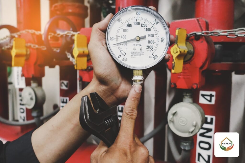
- The 90G-21 reduces inlet pressure to a steady downstream pressure; the datasheet calls for gauges upstream and downstream and a relief valve of at least 1/2 in downstream.
- The 134-05 opens or closes on an electrical signal from the detection or release panel; its UL/ULC listing applies to the 100G/2100G main valve (3–12 in) with the 134-05 trim.
In this article
- What is a fire pump relief valve and when is one required?
- Cla-Val 50B-4KG1 relief valve: how it works and key specifications
- How do you size a fire pump relief valve?
- WC-1 waste cone: why the discharge must be visible
- Cla-Val 90G-21 pressure reducing valve: when you need it instead
- Cla-Val 134-05 solenoid deluge valve: how a deluge system is released
- Quick comparison: which Cla-Val valve does what?
- Common mistakes in pump room and deluge valves
- FAQ
- Conclusion
What is a fire pump relief valve and when is one required?
A centrifugal fire pump produces its highest pressure at zero flow (churn or shutoff), when it runs against closed valves. Static suction pressure from the tank or city main adds to that. If the total exceeds the rated pressure of system components, something has to limit it.
NFPA 20, the standard for stationary fire pumps, ties the main relief valve mainly to diesel pumps: it is needed where 121% of net rated shutoff pressure plus maximum static suction pressure exceeds the component rating. It also applies to pumps with variable speed drivers, as a safeguard for when the driver defaults to constant rated speed. On a constant-speed electric pump the standard generally does not allow a main relief valve as the fix for overpressure; the answer is a correctly selected pump and components. The designer settles this from the adopted edition and the actual pump data.
In the Kingdom, the Saudi Fire Protection Code SBC 801 is the binding reference; NFPA standards are technical references that the designer or project specification adopts. For pump fundamentals see our NFPA 20 fire pump guide.
Cla-Val 50B-4KG1 relief valve: how it works and key specifications
The Cla-Val Model 50B-4KG1 pressure relief valve (globe), with its angle counterpart 2050B-4KG1, is a pilot-controlled Hytrol main valve. The manufacturer describes it as holding system pressure at the pump discharge within close limits as demand changes, opening fast and closing slowly to dissipate surges at pump start-up and shutdown. It can also serve pressure sustaining, back pressure and unloading functions in a bypass arrangement.
Pilot system
The pilot system is normally closed. The datasheet schematic lists the Hytrol main valve, CRL pressure relief control, X58C restriction assembly, check valve, pressure gauge and X43 Y-strainer. The set point is adjusted on the CRL screw while watching the gauge (clockwise to increase, counterclockwise to decrease), and the screw cover can be sealed against tampering.
Key data
- Approved sizes: 1.5–2.5 in (UL only); 3–8 in (UL and FM).
- Ends: flanged 1.5–8 in, grooved 1.5–8 in, threaded 1.5–3 in.
- Pressure: 150 class to 250 psi in ductile iron and 285 psi in other materials; 300 class to 300 psi in all materials.
- Spring ranges: 10–75, 20–200 or 100–300 psi.
- Materials: epoxy-coated ductile iron ASTM A-536 body and cover, stainless steel trim, cast bronze pilot system, Buna-N rubber, with optional seawater materials including nickel aluminium bronze, 316 stainless and super duplex.
- Temperature: water to 180°F.
The datasheet also recommends the Cla-Val 33ATD air and vacuum valve for fire pump relief valves and the WC-1 waste cone on the valve outlet.
How do you size a fire pump relief valve?
The datasheet includes an NFPA 20-based guideline linking valve size to maximum pump flow. The values below come from the manufacturer’s table; the final size is set by the designer from the NFPA 20 table in the adopted edition and the actual pump rating.
| Valve size | Max pump flow (GPM), Cla-Val table | Cv (globe) | Listing per datasheet |
|---|---|---|---|
| 1.5 in | 100 | 32 | UL |
| 2 in | 250 | 50 | UL |
| 2.5 in | 300 | 85 | UL |
| 3 in | 500 | 115 | UL and FM |
| 4 in | 1000 | 200 | UL and FM |
| 6 in | 2500 | 440 | UL and FM |
| 8 in | 5000 | 770 | UL and FM |
Also confirm the flange class (150 or 300), an end connection that matches the pump room piping, a spring range that brackets the required set point, and horizontal or vertical orientation, which is part of the ordering code.
WC-1 waste cone: why the discharge must be visible
The Cla-Val Model WC-1 waste cone mounts on the outlet of the fire pump relief valve so operators can see water being discharged before it is routed safely to drain.
According to the AZEIDK product page, the cone is manufactured to NFPA 20 for use with UL/FM fire pump relief valves. It has a one-piece, weld-free ductile iron body to ASTM A536-65, fusion-bonded red epoxy coating, two 2 in 316 stainless steel sight windows, and 150# or 300# flat- or raised-face flanges, with optional seawater and severe-service materials.
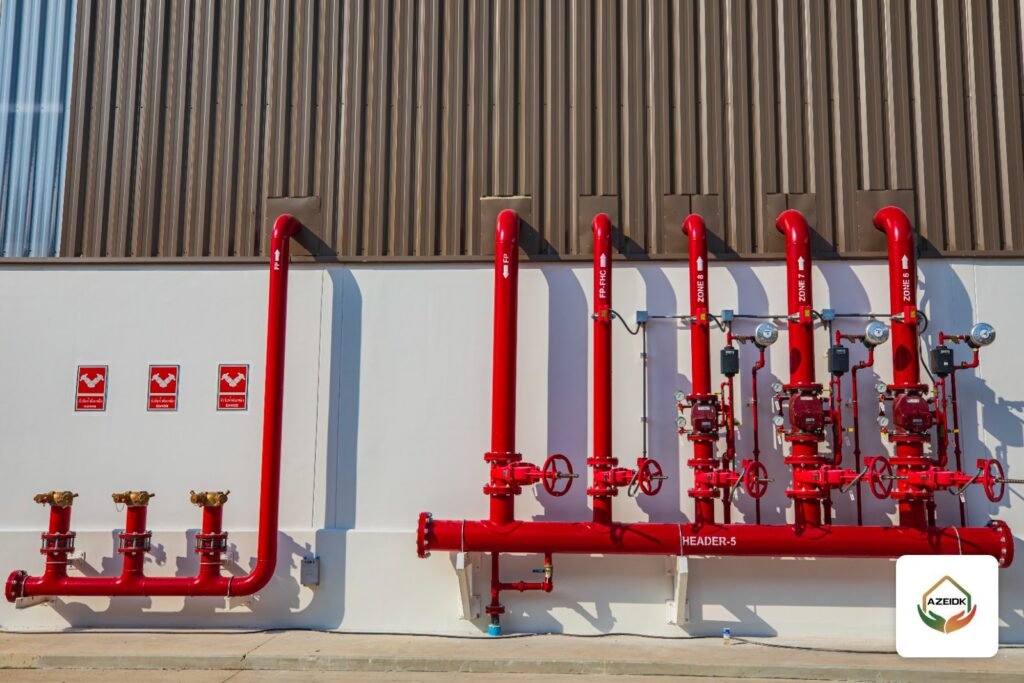
Relief valve discharge is not piped straight back into the pump suction pipe; it normally goes to an open waste cone or back to the dedicated fire water tank, as the design decides. For the full room layout see our fire pump room guide.
Cla-Val 90G-21 pressure reducing valve: when you need it instead
A relief valve protects against overpressure by sending water out of the system. The Cla-Val Model 90G-21 pressure reducing valve (globe) and 90A-21 (angle) sit in the supply path and reduce a higher inlet pressure to a steady lower downstream pressure regardless of flow or inlet changes. If downstream pressure exceeds the set point, the main and pilot valves close drip-tight; with the optional check feature the valve closes on pressure reversal to prevent backflow.
Typical applications in the datasheet include fire pump regulation, system pressure regulation and foam, and the product page adds pressure zoning of standpipe and sprinkler systems in high-rise buildings.
Installation conditions in the datasheet
- UL requires pressure gauges upstream and downstream of the PRV.
- A relief valve of at least 1/2 in must be installed downstream, with adequate drainage.
- Vertical or horizontal installation is allowed.
- Listed adjustment range: 50–175 psi for 1.5 in and 2.5–12 in; 30–165 psi for 2 in.
- Minimum differential at maximum flow: 20 psi (10 psi for 2 in).
- Sizes: flanged 1.5–12 in, grooved 1.5–8 in (to 6 in in angle), threaded 1.5–3 in, with the same pressure classes as the relief valve.
Cla-Val 134-05 solenoid deluge valve: how a deluge system is released
In a deluge system the nozzles are open and the piping downstream of the valve is dry, so water flows to the whole area at once on release. The Cla-Val Model 134-05 solenoid operated deluge valve is an on-off valve that responds to an electrical signal at its solenoid pilot. It combines a 100G/2100G Hytrol main valve, a three-way solenoid valve and an auxiliary pilot that pressurises or vents the main valve diaphragm chamber.
- Mode: normally open (de-energise to open) or normally closed (energise to open).
- Listing: the datasheet notes that UL and ULC listings apply to the 100G/2100G main valve fitted with the 134-05 trim, in 3–12 in sizes.
- Sizes: globe flanged 3–12 in, globe grooved 3–8 in, angle flanged 3–12 in.
- Voltages: 24, 120, 240, 480 V AC 60 Hz; 110, 220 V AC 50 Hz; 6, 12, 24, 120, 240 V DC.
- Solenoid enclosure: NEMA 1, 2, 3, 3S, 4, 4X general purpose watertight or NEMA 6, 6P, 7, 9 watertight; an explosion-proof version is available at extra cost.
- Seawater service uses the 100GS/2100GS main valve.
The product page lists deluge and pre-action systems released from a detection or suppression panel, water spray for transformers and tank areas, and foam systems. For system comparisons see wet, dry, pre-action and deluge systems.
Quick comparison: which Cla-Val valve does what?
| Product | Location | Function | Sizes per datasheet |
|---|---|---|---|
| 50B-4KG1 / 2050B-4KG1 | Pump discharge | Relieve excess pressure, limit surges | 1.5–8 in |
| WC-1 | Relief valve outlet | Show discharge and route it to drain | To suit the relief valve |
| 90G-21 / 90A-21 | After the pump or at pressure zones | Reduce to a steady downstream pressure | 1.5–12 in |
| 134-05 | Deluge system inlet | Open water on an electrical release signal | 3–12 in |
Common mistakes in pump room and deluge valves
- Fitting a main relief valve on a constant-speed electric pump to mask overpressure instead of revisiting pump and component selection.
- Sizing the relief valve from the discharge pipe size rather than pump flow and the NFPA 20 table.
- Piping relief discharge into the suction pipe, or into a closed drain where flow cannot be seen.
- Setting the relief valve without a calibrated gauge, or leaving the adjustment cover unsealed.
- Installing a PRV without upstream and downstream gauges or without the small downstream relief valve the datasheet requires.
- Submitting a deluge valve as UL listed without confirming that the size and trim match the listing, or with a solenoid voltage that does not match the release panel.
For other valve types in the network see fire protection valves in Saudi projects.
FAQ
Does every fire pump need a relief valve?
No. NFPA 20 ties it mainly to diesel and variable-speed pumps where maximum pressure would exceed the component rating. The designer decides from the pump data and suction pressure.
What is the difference between a relief valve and a pressure reducing valve?
A relief valve dumps excess water out of the system when the set point is exceeded; a PRV stays in the supply path and holds a steady lower pressure downstream.
Is the 50B-4KG1 FM approved?
Per the datasheet, 3–8 in sizes are UL listed and FM approved; 1.5–2.5 in sizes are UL listed only.
Why install a WC-1 waste cone?
So water leaving the relief valve is visible to operators and routed safely to drain. It is designed for UL/FM fire pump relief valves.
How does the 134-05 deluge valve open?
On an electrical signal to its solenoid from the detection or release panel. Order it normally open or normally closed, at the panel’s voltage.
Conclusion
The relief valve and waste cone protect the pump room from overpressure and make discharge visible, the PRV controls downstream pressure in high zones, and the solenoid deluge valve links a deluge system to its release panel. Each selection starts from the datasheet: listed size, pressure class, set-point range, end connection and solenoid voltage. The Cla-Val page at AZEIDK lists all four products with the official catalogue for each.
Equipping a pump room or deluge system and need Cla-Val valves selected and submitted? Send your pump data and drawings to AZEIDK’s technical supply team for a selection review. Contact the AZEIDK team
Related guides
- NFPA 704 Diamond (nfpa diamond): What the Colours and Numbers Mean and Where It Goes in a Facility
- Fingerprint Attendance Device Price in Saudi Arabia: What Drives the Cost (Fingerprint or Face, Headcount, Software, Installation) and How to Compare Quotes
- Saudi Civil Defense Requirements for Buildings and Facilities
- CCTV Camera Price in Saudi Arabia (KSA): What Drives CCTV System Cost for Facilities and How to Compare Installation Quotes