

A fire pump control panel wiring diagram shows four groups of terminals: incoming power and motor leads, the pressure sensing connection, the alarm signals sent to the fire alarm panel, and, on diesel controllers, the battery and engine circuits. This article explains what each group does, what should appear on the diagram and what the consultant checks. It is descriptive only: actual wiring always follows the controller manufacturer’s field connection diagram and is carried out by a qualified electrician. For the pumps themselves, see the fire pumps available from AZEIDK, and for controller types and selection, see our article on fire pump controllers.
Key takeaways
- On an electric controller, supply conductors land on the line side of the isolating switch and the motor leads on the load side of the contactor.
- NFPA 20 covers electric drive controllers in Chapter 10, engine drive controllers in Chapter 12 and power supplies for electric drive pumps in Chapter 9.
- The core electric controller signals to the fire alarm panel are pump running, loss of phase, phase reversal, controller trouble and, where fitted, alternate source signals.
- A diesel controller sends engine running, switch in off or manual, and a trouble signal to a remote location.
- The jockey pump has its own controller and is never supplied from the fire pump controller.
In this article
- What does a fire pump control panel wiring diagram show?
- Power connection for electric fire pump controllers
- Pressure sensing line and pressure switch
- Alarm signals from the electric controller to the fire alarm panel
- Diesel fire pump controller wiring: batteries and engine terminals
- Remote signals from the diesel controller
- Remote start and deluge valve inputs
- What the consultant checks on the wiring diagram
- Common fire pump controller wiring mistakes
- Frequently asked questions
- Conclusion
What does a fire pump control panel wiring diagram show?
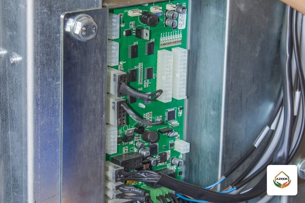
A fire pump controller arrives factory wired internally, with a diagram showing the terminals the contractor connects on site. The same groups appear on most listed controllers, although terminal numbers vary between manufacturers:
| Terminal group | What connects to it | Electric or diesel |
|---|---|---|
| Incoming power | Supply cables from the normal source, and from the alternate source where a transfer switch is used | Electric |
| Motor output | Pump motor cables from the load side of the contactor | Electric |
| Pressure sensing | Sensing line from the discharge piping to the controller’s pressure sensor | Both |
| Remote alarm signals | Dry contacts wired to the fire alarm panel or a monitoring system | Both |
| Remote start inputs | Remote start push button, or a contact from a deluge valve or another system | Both, model dependent |
| Batteries and engine terminals | Two battery sets and the engine connections: fuel, speed, oil, temperature and crank | Diesel |
| Charger supply | AC supply to the battery chargers inside the controller | Diesel |
If you are looking for a fire pump control panel wiring diagram PDF, it is normally part of the datasheet or installation manual for that exact model, and a copy is often fixed inside the controller door. Do not use a diagram from another model: terminal numbers and supply arrangements differ.
Power connection for electric fire pump controllers
The installation manual of one listed full service controller instructs that supply conductors be connected to the line side of the isolating switch in the correct phase sequence, and motor conductors to the load side of the motor contactor. The isolating switch is interlocked so the door cannot be opened while it is closed, and no work starts inside the cabinet until the supply is isolated and locked off.
The supply rules themselves come from NFPA 20 Chapter 9 and, where the designer adopts it, NEC Article 695:
- A direct connection from the source to the fire pump controller is the most reliable arrangement; any added disconnect needs justification and supervision.
- No protective devices are installed on the load side of the power transfer switch in the pump circuit.
- Voltage drop at the controller during motor starting is limited to 15%, and at the motor terminals when running at 115% of full load current to 5% (NEC 695.7).
- The fire pump controller does not supply the jockey pump (NEC 695.6(I)).
- Controller location: according to EC&M’s guide to fire pump electrical design, NFPA 20 and the NEC require the controller to be as close as practical to, and within sight of, the motor; check the wording in the edition adopted for the project.
After connection, the commissioning team bumps the motor to confirm rotation; any correction is made with the supply isolated and per the manufacturer’s instructions. This is part of installation and implementation, followed by testing.
Pressure sensing line and pressure switch
The controller starts the pump automatically when system pressure drops, and it reads that pressure through a sensing line from the discharge piping to its pressure sensor. Modern controllers mostly use an electronic pressure transducer; some use a pressure switch with separate start and stop set points.
The diagram shows where the sensing line connects and the fitting size the manufacturer specifies. Intertek’s update notice on the 2019 edition of NFPA 20 states that water piping shall not be extended into the controller. The manual of a listed diesel controller requires the sensing line to be thoroughly flushed before it is connected to the controller, to keep debris out of the internal piping.
The jockey pump has its own controller and pressure switch, set to run before the main pump. Settings are covered in Jockey Pumps: Sizing and Start/Stop Pressure Settings.
Alarm signals from the electric controller to the fire alarm panel
Where the pump room is not constantly attended, NFPA 20 Chapter 10 (2019 edition, as summarised in Intertek’s update notice) requires an electric controller to provide signals at a point of constant attendance, mainly:
- Pump or motor running.
- Loss of any phase at the line terminals of the motor contactor.
- Phase reversal, with the circuit powered from a separate reliable supervised source or from the motor power reduced to 125 V or less.
- Controller or system trouble.
- Where an alternate source is provided: a signal that the controller is on the alternate source, and a signal that the alternate source isolating switch or breaker is open or tripped.
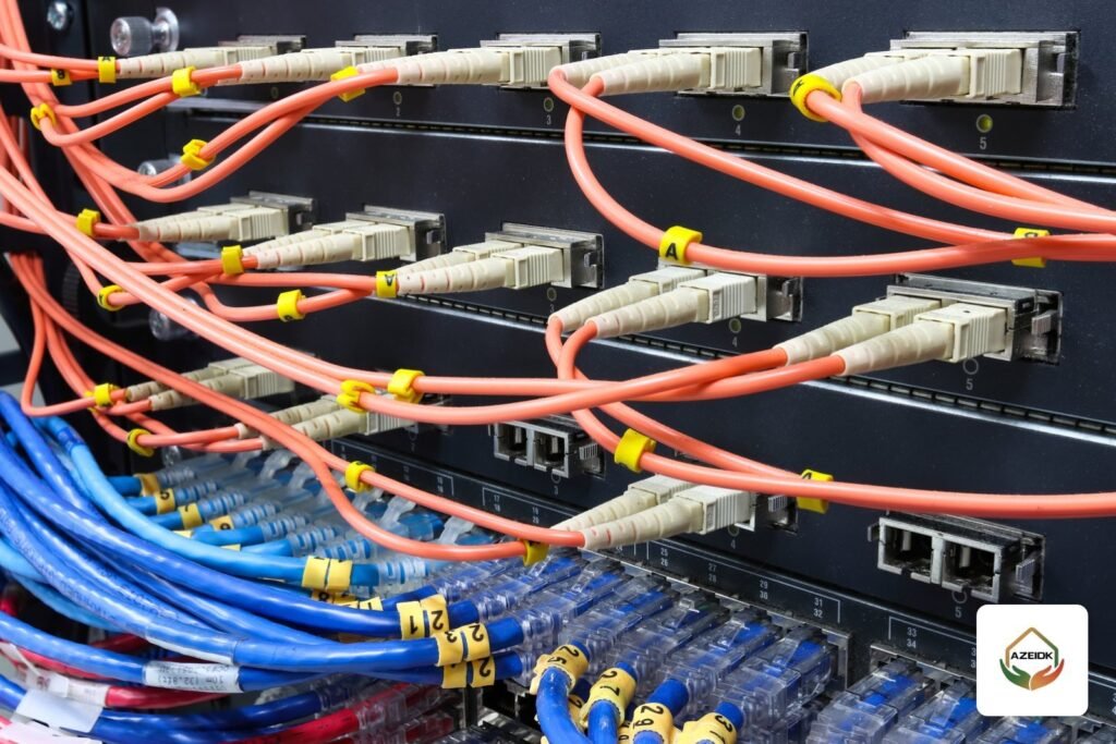
These are dry contacts on the user terminal strip. On an addressable fire alarm panel they are usually received by monitor (input) modules, with each point programmed with a clear label. See fire alarm input/output modules for how these interfaces work. Whether each signal is treated as an alarm, supervisory or trouble condition is set by the designer in the interface matrix according to the code adopted for the project.
Diesel fire pump controller wiring: batteries and engine terminals
A diesel controller does not run an electric motor; it cranks the engine from batteries and monitors it. Its wiring diagram therefore looks different:
- Two battery sets: the controller alternates between them on each crank attempt. One manufacturer’s specification notes that a set is locked out if it falls below 60% of rated voltage while cranking.
- Chargers: fed with AC from terminals inside the controller. The 2019 edition of NFPA 20 requires two means of recharging the batteries.
- Engine connections: engine junction box terminals are wired to like-numbered controller terminals with correctly sized stranded wire.
Typical engine terminal functions, as listed in the manual of one listed diesel controller (numbers differ between manufacturers):
| Terminal function | Purpose |
|---|---|
| Fuel solenoid supply | Energised on a start call to open fuel and cooling water |
| Speed switch: engine running | Ends cranking once the engine runs |
| Speed switch: overspeed | Signals an overspeed shutdown |
| Oil pressure switch | Low oil pressure alarm |
| Water temperature switch | High engine temperature alarm |
| Crank 1 and Crank 2 | Crank from battery 1 or battery 2 |
| Battery 1 and battery 2 voltage | Monitor the presence of each set |
The same manual warns never to disconnect the batteries while AC power is on to the controller. For the full diesel package, see Diesel Fire Pump Components and NFPA 20.
Remote signals from the diesel controller
Under NFPA 20 Chapter 12 (2019 edition), where the pump room is not constantly attended, at least three signals are transmitted from a diesel controller to a remote location: engine running, controller main switch in off or manual, and a trouble signal that may combine controller and engine faults. The detail, such as failure to start, low oil pressure, high temperature, battery and charger faults, is shown on the controller’s own indicators in the pump room.
Some controllers offer separate contacts for individual faults such as battery failure or failure to start. If the owner wants each fault on the fire alarm panel, specify it before procurement so it appears on the diagram and the contact list.
Remote start and deluge valve inputs
Most controllers accept start commands from outside. In the manual of one listed diesel controller, the remote start push button is close-to-start, while the deluge valve or other remote automatic start input is open-to-start. In the manual of an electric controller, a pump started remotely can only be stopped locally at the controller.
How each input works and is enabled varies between manufacturers, so it is defined in the submittal and every input is tested during commissioning.
What the consultant checks on the wiring diagram
- The field connection diagram for the exact model supplied, not a generic drawing.
- The single line diagram for the pump supply, alternate source and transfer switch.
- The contact list: number and type of signals, which are individual and which are combined.
- The interface matrix with the fire alarm panel: each signal, its receiving module and its label.
- Listing of the controller for fire pump service (UL or FM) for the model and starting method.
- The sensing line drawing and connection point.
These documents are completed under testing, commissioning and handover, where each signal is proven to arrive at the fire alarm panel.
Common fire pump controller wiring mistakes
- Feeding the jockey pump controller from inside the fire pump controller.
- Wiring only one common trouble signal and leaving pump running or phase reversal unconnected.
- Adding a protective breaker after the transfer switch in the pump circuit.
- Connecting the sensing line to the controller before it is flushed.
- Working from another model’s diagram, so engine terminal numbers or deluge input logic do not match.
Frequently asked questions
Where can I find a fire pump control panel wiring diagram PDF?
In the datasheet or installation manual for the model supplied, and often inside the controller door. Ask the supplier for it with the submittal before cabling starts.
Which fire pump signals go to the fire alarm panel?
For an electric pump: running, loss of phase, phase reversal, controller trouble and alternate source signals where fitted. For a diesel pump: engine running, switch in off or manual, and trouble.
Can the jockey pump be fed from the fire pump controller?
No. The jockey pump has its own controller, and NEC 695.6(I) does not permit supplying it from the fire pump controller.
How many batteries does a diesel fire pump controller need?
Two battery sets, which the controller alternates between when cranking, with two means of recharging.
Can a technician wire the controller without the manufacturer’s diagram?
No. Wiring is done by a qualified electrician to the manufacturer’s diagram for that model, with the supply isolated and locked off.
How does a diesel controller diagram differ from an electric one?
The electric diagram centres on incoming power, the motor and the transfer switch. The diesel diagram centres on batteries, chargers and engine terminals such as fuel, speed and crank.
Conclusion
A fire pump control panel wiring diagram answers four questions: where the power comes from, how the controller senses system pressure, which signals reach the fire alarm panel, and how a diesel controller manages its batteries and engine. The reference is always the manufacturer’s diagram for the model supplied, the work belongs to a qualified electrician, and every signal is tested before handover. Checking these signals can also form part of a fire, safety and alarm systems maintenance contract.
Fitting out a pump room or reviewing the pump to fire alarm interface? Send the pump and controller models with the drawings, and our team will review the signal list and connection requirements with you. Talk to the AZEIDK team
Related guides
- Fire Alarm System Installation in Saudi Arabia: Stages, Cabling and Pre-Approval Checks
- Common Intercom Faults and Fixes: Audio, Video, Door Release and Mobile App
- Sprinkler Pipe Schedule Chart, Head Spacing and Sprinkler Flow Under NFPA 13
- AFC ACV-300 Wet Alarm Check Valve: Models, Trim Components and Installation in Sprinkler Systems