

Fire alarm system installation in Saudi Arabia runs in five stages: review of the approved drawings and the site, conduit and cable installation, control panel and power supply, field devices (detectors, manual call points and notification appliances), and a self-inspection before acceptance testing and the Civil Defense inspection. Each stage should end with a record of what was done.
This article is about site execution: the order of work, what to check at each stage, and the faults that usually surface at handover. It is part of the installation and implementation service AZEIDK provides for fire alarm and firefighting systems. System selection, cable types, loop design and detailed commissioning tests each have their own article, linked where relevant.
Key takeaways
- Do not start containment before the shop drawings and the material submittals are approved.
- Install and test conduit and cables before devices go in. Insulation resistance testing is done with devices disconnected.
- Fit smoke detector heads after construction cleanup, or protect them with covers if they must be live earlier.
- Section 907 of the Saudi Fire Protection Code SBC 801 (2024 edition) is the Saudi reference for fire alarm and detection systems. NFPA 72 is the technical reference the designer adopts.
- A full contractor self-inspection before acceptance testing cuts the number of comment rounds from the consultant and Civil Defense.
In this article
- What are the stages of fire alarm system installation on Saudi projects?
- What should you check before containment starts?
- How are conduit and cables installed?
- How are the panel and power supply installed?
- How are detectors, call points and notification appliances installed?
- What checks are needed before approval and handover?
- Common fire alarm installation mistakes
- How AZEIDK supports fire alarm installation
- Frequently asked questions
- Conclusion
What are the stages of fire alarm system installation on Saudi projects?
The table shows the usual sequence on site and what is handed over at the end of each stage. The order may shift with the project programme, but the rule holds: no stage is closed until it is documented.
| Stage | Main works | Output or record |
|---|---|---|
| 1. Preparation | Review approved drawings, survey the site, approve materials, coordinate with electrical, mechanical and ceiling trades | Approved shop drawings, approved submittals, execution plan |
| 2. Containment and cabling | Install conduit, back boxes and supports; pull and label cables | Continuity and insulation test record per circuit |
| 3. Panel and power | Mount the panel, connect the dedicated circuit, install batteries | Confirmed power source and battery calculation |
| 4. Field devices | Fit bases, then detectors, call points, notification appliances and interface modules | Address list with actual locations |
| 5. Pre-acceptance check | Self-inspection, initial programming, snag clearance, handover file | Ready for acceptance testing, as-built drawings |
What should you check before containment starts?
Most installation problems start with a drawing that was never checked against the site. Before the first conduit goes up, the installation team reviews:
- Approved drawings: detector, call point and notification appliance locations; zones or loops; main panel and repeater locations.
- False ceilings: structural and false ceiling levels, and the positions of air diffusers, lights and sprinklers, so detectors do not clash with other services.
- Material approval: the datasheet for every device and cable, and compatibility of detectors and modules with the selected panel.
- Interfaces: lifts, smoke extract fans, AHUs, access-controlled doors and any gas suppression system. Each needs an interface module, and its location should be fixed early.
If the project is still choosing between conventional and addressable, read the conventional vs addressable selection guide before the drawings are approved. Changing system type after cabling means redoing much of the work.
How are conduit and cables installed?
Conduit, boxes and supports
Conduit and back boxes follow the shop drawing routes, with regular fixings and pull boxes on long runs and at changes of direction. Keep fire alarm routes separate from power cables and do not share a conduit or tray with them, following the project specification and the manufacturer’s instructions. Where fire-resistant cable is used, supports and fixings must be metal. Plastic clips can melt and let the cable drop.
Pulling and labelling
Pull each cable in one length between devices, with no mid-run joints, and label both ends with the loop or zone number. For Class A circuits, NFPA 72 requires the outgoing and return paths to be routed separately, with limited exceptions for short lengths where the conductors enter device or panel enclosures. Take the exact limits from the edition adopted for the project. Loop capacity, isolators and device distribution are covered in addressable fire alarm loop design.
Loop limits come from the panel’s own datasheet. For example, the AZEIDK page for Context Plus FirePlus addressable panels gives a maximum loop length of 1 km, a cable cross-section of 1.5 to 2.5 mm², and up to 126 devices per loop. Whether the cable is standard shielded or fire-resistant is a design decision; see the fire alarm cables guide. AZEIDK supplies Fire World FPLR fire alarm cable and Falcon Gold fire alarm cable.
Testing cables before devices are connected
Straight after pulling, test every circuit for continuity, short circuit, insulation resistance and earth leakage with the devices disconnected. A high-voltage insulation tester (megger) can damage detectors and modules. Record the results per circuit. This record is the first thing anyone asks for when an earth fault appears later.
How are the panel and power supply installed?
Mount the panel in the approved location, usually near the main entrance, a control room or a security room, at a height where the display can be read and operated, and away from moisture and excess heat. The FirePlus page states that the 5- and 6-loop models need a separate battery cabinet (ULP-BCG), so reserve wall space for it before installation.
Primary power comes from a dedicated branch circuit that serves no other loads. How its disconnecting means is marked, protected against accidental switch-off and identified at the panel follows the edition adopted for the project and the project specification, and should be agreed with the consultant before installation. Battery capacity is calculated from actual system load, not estimated.
How are detectors, call points and notification appliances installed?
Bases first, heads later
Fit and wire detector bases during finishing works, but hold back smoke detector heads. Standard practice is not to fit smoke detector heads until construction cleanup by all trades is complete. Where the authority requires detection during construction, the detectors are protected in line with the manufacturer’s instructions. Dust covers reduce contamination but do not prevent it, so check detector cleanliness and sensitivity before handover.
Spacing and heights
- Manual call points (MCP): the operable-part height, the positions near exits and the maximum travel distance come from the approved drawings, based on the code and edition adopted. The technician keeps to the set level and does not change it on site.
Several changes summarised by Consulting-Specifying Engineer for the 2025 edition of NFPA 72 bear directly on installation:
- High ceilings: in the 2025 edition of NFPA 72, the prescriptive spacing method for spot-type smoke detectors applies up to 40 ft (about 12.2 m). Above that, a performance-based analysis and design is needed.
- Beams: the 2025 edition treats a girder whose top is within 4 in (about 100 mm) of the ceiling as a beam for detector spacing.
- Notification appliances: the 2025 edition added voltage drop calculations and length criteria for notification circuits in 18.3.7, so the as-installed circuit length must match the calculation.
Any change on site, such as moving a detector away from a diffuser or a beam, goes back to the designer and is recorded on the drawing. It is not left to the technician’s judgement.
Interface modules
Input/output modules are installed close to the equipment they control. According to the same Consulting-Specifying Engineer summary, the 2025 edition of NFPA 72 allows the interface to be up to 20 ft (about 6 m) from the controlled component if the conductors run in metal raceway or metal-armoured cable.
What checks are needed before approval and handover?
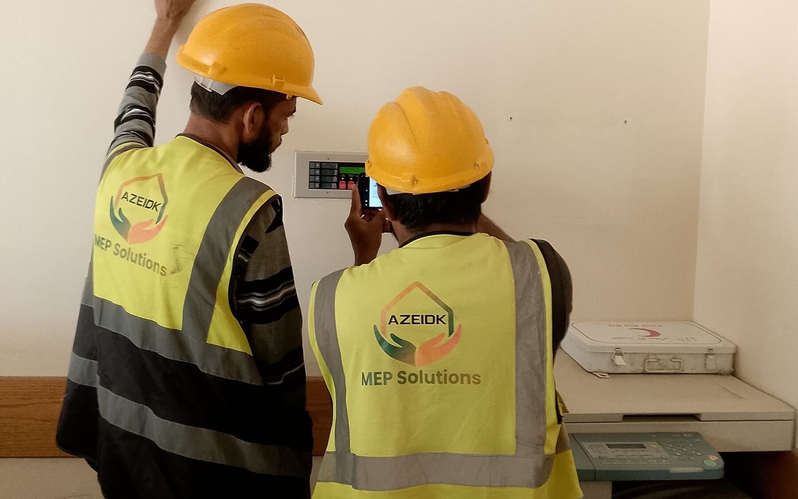
Before inviting the consultant to acceptance testing, the contractor carries out a full self-inspection: device locations match the drawing, every address reads on the panel, the panel is clear of earth and open-circuit faults, notification appliances operate, interfaces work at a basic level, and as-built drawings are updated. Formal device-by-device testing, sound level measurement, battery tests and the record of completion are explained in fire alarm commissioning and acceptance testing.
On the regulatory side, Section 907 “Fire Alarm and Detection Systems” of the Saudi Fire Protection Code (SBC 801-CR-2024) covers these systems. The Implementing Regulations of the Saudi Building Code Application System provide for inspections to follow the construction stages in sequence. The Civil Defense licence is issued through the Salamah platform; see the Civil Defense fire safety approval guide.
Common fire alarm installation mistakes
- Starting containment on a design drawing that was not coordinated with ceilings and HVAC, then moving devices after the ceiling is closed.
- Running fire alarm cable in a power conduit, or making joints in the run without a box.
- Routing the outgoing and return legs of a Class A loop in the same conduit.
- Megger testing after devices are connected.
- Fitting smoke detector heads during painting and gypsum works without protection.
- Leaving cables unlabelled, which makes later earth fault tracing slow.
- Handing over without as-built drawings that match actual locations and addresses.
How AZEIDK supports fire alarm installation
AZEIDK installs Context Plus addressable and conventional fire alarm systems, from drawing review and material preparation to installation, initial inspection and handover for testing. We supply Context Plus panels, detectors, call points and interface modules, and fire alarm cable from Fire World and Falcon Gold, each with its datasheet. Programming, testing and commissioning, and Civil Defense approval support follow where needed.
Frequently asked questions
How long does fire alarm installation take?
It depends on building size, device count, ceiling readiness and coordination with other trades. The programme is set after a site survey and drawing review.
Can detectors be installed before finishing works end?
Bases and wiring go in during finishing works. Smoke detector heads wait until cleanup, or are fitted with covers if they must be live earlier.
When is cable insulation testing done?
After the cables are pulled and before devices are connected, because the test voltage can damage detectors and modules.
Is NFPA 72 mandatory in Saudi Arabia?
The legal reference is the Saudi Building Code, including SBC 801 and its Section 907. NFPA 72 is a technical reference adopted by the designer or named in the project specification.
What documents are handed over after installation?
As-built drawings, cable test records, the address list and device datasheets, followed by the acceptance test records after commissioning.
Conclusion
The quality of a fire alarm installation shows on test day, but it is decided much earlier: a coordinated drawing, tested and recorded cable routes, a panel on a dedicated circuit, and detectors fitted at the right time. Following the stages in order and documenting each one reduces comments at handover and at the Civil Defense inspection.
Need a fire alarm system installed? Send us the approved drawings or a description of the site, and we will review the installation scope and materials with you. Talk to the AZEIDK team