

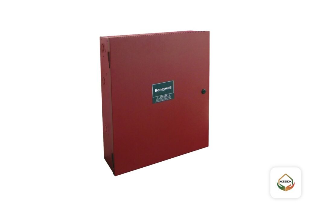
A fire alarm booster power supply (NAC booster, NAC power extender) is a separate unit with its own charger and batteries that drives sounders and strobes when their load is more than the fire alarm panel can deliver. You need one when the total alarm current of the notification appliances exceeds the panel outputs, or when distance and voltage drop stop you from running the circuit from the panel room. Sizing takes three steps: alarm current per circuit, battery capacity, then voltage drop to the last device. It is part of the fire alarm system design, not a box added on site without calculations.
Key takeaways
- A NAC (Notification Appliance Circuit) is the circuit that powers sounders, strobes and sounder strobes.
- The booster never decides when to alarm. The main panel triggers it through a NAC output, an output module or a data bus.
- Each booster has its own battery calculation. Its load is added to the panel batteries only if it actually draws from the panel.
- Every booster fault (AC loss, battery, open or short on a NAC) must report to the main panel.
- Where more than two strobes are in one field of view they must flash in sync, even if some are on the panel and some on the booster.
In this article
- What is a fire alarm booster power supply?
- When do you need a NAC booster?
- How does the panel trigger the booster?
- How do you make sure booster faults reach the panel?
- How do you size the booster load and batteries?
- NAC voltage drop: why a design fails even when the current is fine
- Strobe synchronization: the point people forget when adding a booster
- Where is the booster installed and how is it powered?
- Common mistakes with NAC boosters
- Frequently asked questions
- Conclusion
What is a fire alarm booster power supply?
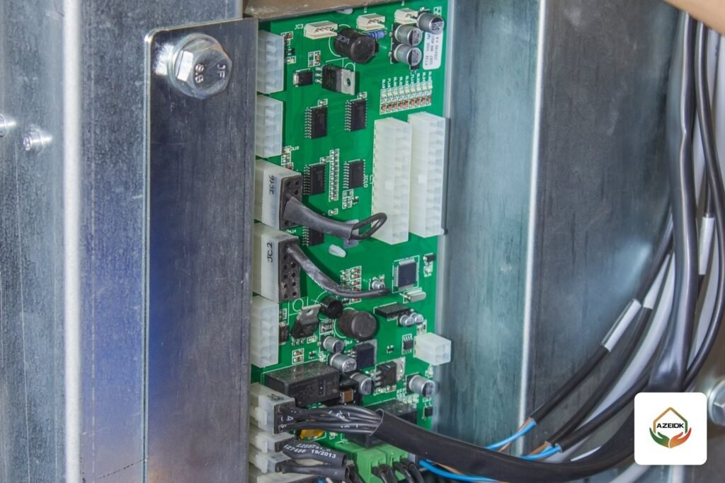
Conventional and addressable panels have dedicated notification outputs. Each output has a current limit, and the panel has an overall limit set by its power supply and charger. In a large building the number of sounders and strobes grows and the alarm current goes past those limits. A booster solves this: a separate enclosure with a 24 VDC supply, a charger, batteries and several supervised NAC outputs.
Manufacturers use different names: NAC booster, NAC power extender, remote power supply. The job is the same. It moves the notification load from the panel to a source close to the devices, while control and supervision stay with the main panel. The booster must be listed for fire alarm use and compatible with the panel. As an example, one manufacturer’s datasheet lists its NAC power extender to UL 864 (control units and accessories for fire alarm systems) and rates it at 8 A total at 24 VDC, with 2.5 A per output.
When do you need a NAC booster?
The rule is simple: if the total alarm current, with a spare margin, is more than the panel outputs can supply, you need a booster. On Saudi projects this usually shows up in:
- Multi-storey buildings with many sounder strobes, such as hotels, hospitals and malls.
- Large warehouses and factories, where the run from the panel room to the last device is long and voltage drop goes past the limit.
- High-noise areas that need louder sounders and brighter strobes, which draw more current.
- Extensions to existing buildings, where the current panel cannot take new devices and the owner does not want to replace it.
- Addressable systems with loop-powered sounders where the loop load is close to its limit.
An example from Context Plus addressable panels: the XFP501 datasheet gives a 3 A total output limit and 500 mA maximum per loop, as covered in our fire alarm battery calculation article. When device load approaches these figures, the designer looks at moving part of the notification load to NAC circuits fed by a booster.
How does the panel trigger the booster?
A booster does not start on its own. There are three common trigger methods, and panel compatibility decides which one you can use:
| Trigger method | How it works | What to check |
|---|---|---|
| From a panel NAC output | The panel NAC output wires to the booster input. The booster follows it (on, silence, tone pattern) | The booster input appears to the panel as a load. Check the end-of-line (EOL) arrangement in the installation manual |
| From an addressable output module | The panel programs a relay or control module to start the booster from the cause and effect matrix | Lets different zones start at different times for phased evacuation |
| Over a same-brand data bus | The booster is part of the panel network. Its address and faults show on the panel display | Needs a booster from the same manufacturer, compatible with the panel firmware |
In every case the panel decides and the booster executes. Check the cause and effect matrix to see which booster outputs operate for which alarm.
How do you make sure booster faults reach the panel?
A booster that does not report its faults is worse than no booster, because part of the building can lose notification with nobody knowing. Listed boosters have trouble relays for AC failure, low or missing battery, ground fault, and open or short on the NACs. These outputs wire to a monitored input on the panel or to an addressable input module, so the fault shows on the panel display with the booster name and location.
At handover, cut the AC supply to the booster and confirm the panel shows a fault. Disconnect the battery and repeat. Open the end of a NAC and confirm that fault too. These checks belong to testing, commissioning and handover.
How do you size the booster load and batteries?
The logic is the same as for the panel batteries, but the calculation is separate. The technical reference designers normally adopt is NFPA 72: 24 hours of standby on battery, then 5 minutes of full alarm load (15 minutes for emergency voice systems), plus a safety margin. The steps:
- Add up the alarm current of every device on each circuit from its datasheet, at the actual voltage and setting (candela and tone).
- Check each circuit is below the output limit and the total is below the booster limit, with spare capacity for future devices.
- Take the booster standby current from its datasheet and add any auxiliary loads it feeds.
- Capacity = (standby current × 24 h) + (alarm current × alarm time), multiplied by the safety margin of the NFPA 72 edition adopted on the project.
- Pick the next standard battery size up and confirm the booster charger accepts it.
Worked example with assumed values
These values are for illustration only. On a real project they come from datasheets. A warehouse floor has 60 sounder strobes drawing 120 mA each in alarm. Total load is 7.2 A. The panel cannot carry it, so you choose a booster rated 8 A total and 2.5 A per output.
| Item | Value |
|---|---|
| Circuit split | 4 circuits × 15 devices = 1.8 A per circuit (below 2.5 A) |
| Total load | 7.2 A (below 8 A) |
| Booster standby (assumed) | 0.1 A × 24 h = 2.4 Ah |
| Alarm | 7.2 A × 5 min (0.083 h) = 0.6 Ah |
| Total before margin | 3.0 Ah |
| With 25% margin | 3.75 Ah, so you choose two 12 V 7 Ah batteries in series |
The 25% margin follows the 2022 edition of NFPA 72. The 2010 to 2019 editions asked for 20%. Use the edition adopted on your project.
NAC voltage drop: why a design fails even when the current is fine
The current can be within limits and the last strobe still does not work properly, because the voltage at that device is below its minimum. So voltage drop is calculated for every circuit. California HCAI guidance (PIN 63) says the calculation starts from the panel output with a fully depleted battery, giving 20.4 V for a 24 V panel, and that the voltage at each appliance must not drop below its listed minimum.
With assumed values: if the device minimum is 16 V, the allowed drop is 4.4 V. Drop ≈ current × 2 × circuit length × conductor resistance per metre. With all the load lumped at the far end (worst case), 1.8 A and an assumed 12 ohm per km conductor, the maximum length is about 100 m. If you need more, you have three options: a larger cable, splitting the circuit, or moving the booster closer to the devices. This is where a booster really pays off: placing it on the same floor or zone shortens the circuits.
Class A and Class B wiring, isolators and loop voltage drop are covered in the addressable loop design article, and fire-rated cable selection in the fire alarm cables and circuit integrity guide.
Strobe synchronization: the point people forget when adding a booster
NFPA 72 requires strobes to flash in sync where more than two are in one field of view. The problem appears when some strobes in a corridor are on a panel circuit and others on a booster circuit. If the booster does not support the sync protocol used by the devices and the panel, the two groups flash at different rates. The fix is to choose a booster that supports the device sync protocol and set it to follow the panel sync signal, or to lay out devices so two sources never share one field of view.
Where is the booster installed and how is it powered?
- In a protected, accessible location such as an electrical or service room on the same floor, not above a false ceiling.
- From a dedicated fire alarm branch circuit, clearly identified at the distribution board.
- With its batteries in its enclosure or in a listed battery box next to it, marked with the installation date.
- With its location and number shown on the as-built drawings and in the cause and effect matrix.
Common mistakes with NAC boosters
- Adding sounders to an existing circuit without recalculating current and voltage drop.
- Not wiring the trouble output to the panel, so the booster loses power and nothing shows on the display.
- Batteries smaller than calculated because the larger battery does not fit the enclosure.
- A booster that does not support the strobe sync protocol.
- Leaving booster batteries out of the preventive maintenance programme, so only the panel batteries get tested.
Frequently asked questions
What is NAC in a fire alarm system?
NAC stands for Notification Appliance Circuit. It is the circuit that powers sounders, strobes and sounder strobes and operates them in alarm. The panel supervises it for opens and shorts.
What is the difference between a booster and a sub-panel?
A sub-panel receives detector signals and makes decisions. A booster has no detectors and decides nothing. It only operates notification appliances when the panel tells it to.
Does an addressable fire alarm system need a booster?
Not always. If sounders are loop-powered and the load is within the loop and panel limits, you do not need one. You need one when the load exceeds those limits or when conventional notification appliances run on NAC circuits.
Are booster batteries counted with the panel batteries?
No. Each booster has its own calculation because it carries its own batteries. Only what the booster draws from the panel, such as the output module that triggers it, goes into the panel calculation.
How many sounders can go on one circuit?
There is no fixed number. It depends on the output current limit, the current of each device from its datasheet and the voltage drop to the last device. Calculate all three and use the lowest.
Can the booster be a different brand from the panel?
With a NAC-output or output-module trigger, yes, if the booster is listed for fire alarm use and its datasheet confirms compatibility with the panel, devices and sync protocol. A data-bus connection normally needs a booster from the same manufacturer.
Conclusion
A fire alarm booster power supply solves two problems: current above the panel capacity and distances too long for the allowed voltage drop. Calculate the current per circuit, then battery capacity with the margin of the adopted NFPA 72 edition, then voltage drop from a depleted-battery voltage. After that confirm three things: booster faults show on the panel, strobes are in sync, and booster batteries are on the maintenance schedule. The AZEIDK engineering design and calculations team reviews these figures before supply.
Need the sounder load or booster sizing checked on your project? Send the drawings and device schedule, and the AZEIDK team will check current, batteries and voltage drop. Talk to the AZEIDK team