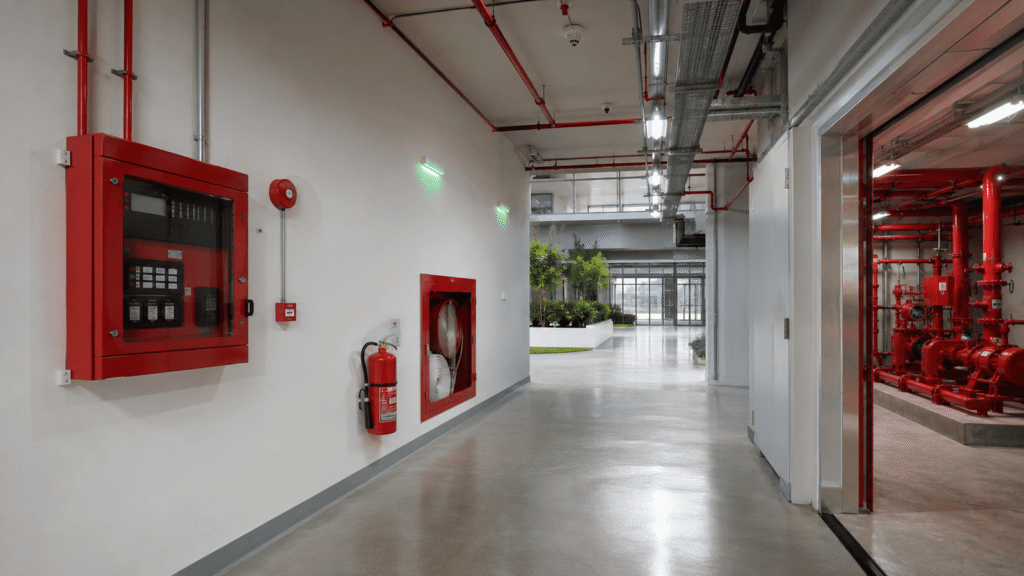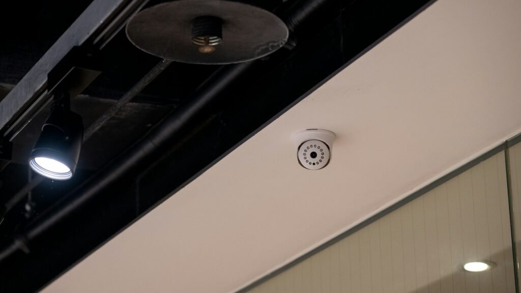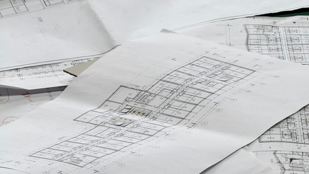

MEP fire safety integration means planning mechanical, electrical and plumbing (MEP) services, fire protection and low-current systems as one coordinated package. Sprinklers, ducts, cable trays and detectors share the same ceilings and shafts, and the fire alarm has to drive heating, ventilation and air conditioning (HVAC) shutdown, smoke control, elevator recall and door release exactly as designed. Most failures appear at the interfaces, so the work comes down to named owners, coordinated drawings and end-to-end testing.
Key takeaways
- Coordinate space first: sprinklers, ducts, cable trays, lighting and detectors share ceiling voids, shafts and plant rooms.
- Wide ducts and trays below ceiling sprinklers often need supplemental sprinklers under them in NFPA 13; settle routes before sprinkler shop drawings.
- Every interface between systems needs a named owner, a defined signal and a test, recorded in the cause and effect matrix.
- A firestop rating belongs to the tested system of barrier, penetrating item and product, not to the sealant alone.
- Plan the integrated test with every contractor in the chain; NFPA 4 sets its requirements in the edition adopted for the project.
In this article
- What MEP, fire safety and low-current integration covers
- Coordination in ceilings, shafts and plant rooms
- Fire-rated walls, floors and penetrations
- Fire alarm interfaces with building systems
- Power, cabling and networks for life safety
- Coordination from design to handover, step by step
- Common site mistakes
- Testing the chain across contractors, and cost
- How AZEIDK helps
- FAQ
What MEP, fire safety and low-current integration covers
Integration works on three layers. The spatial layer fits every service into ceilings, shafts and plant rooms without blocking sprinkler discharge, airflow to detectors or maintenance access. The functional layer defines the signals and commands that pass between the fire alarm and building systems in a fire. The supporting layer covers the power, cabling, containment and networks that keep those links alive.
Several parties own parts of each layer: the consultant, the MEP contractor, the fire protection and low-current contractors, and the elevator and building management system (BMS) vendors. Our BMS and fire alarm integration guide covers the BMS link in detail; this guide covers how the whole package is coordinated.
Coordination in ceilings, shafts and plant rooms
Ceiling voids are where clashes cost the most, because they surface late, after ducts and trays are hung. Settle these points on coordinated drawings before installation:
- Sprinklers and obstructions: NFPA 13 has long required sprinklers below fixed obstructions over 4 ft (1.2 m) wide, such as large ducts and cable trays. The 2025 edition calls them supplemental sprinklers and, per the National Fire Sprinkler Association (NFSA), requires them to be quick response or to have a fast response element.
- Storage sprinklers: early suppression fast response (ESFR) sprinklers are particularly sensitive to obstructions, and NFPA 13 sets stricter obstruction rules for them, so warehouse lights, ducts and trays are fixed around them from the design stage.
- Detectors and air movement: keep smoke detectors out of direct airflow from supply diffusers and return openings, at the distances the adopted NFPA 72 edition and the manufacturer set, and clear of beams that block smoke travel.
- Access: control valves, flow and tamper switches, dampers, duct detectors and fire alarm modules need access panels or clear space for testing.
- Shafts and risers: allocate space for sprinkler risers and standpipes, fire alarm and low-current cabling, and power, keeping fire alarm cables apart from power cables as good practice.
Building information modeling (BIM) with clash detection, or combined services drawings on smaller jobs, is good practice for finding these conflicts before materials reach site.
Fire-rated walls, floors and penetrations
Every pipe, duct, tray and cable that crosses a fire-rated wall or floor opens a path for fire and smoke. A firestop product has no rating by itself: under the UL 1479 and ASTM E814 test methods, the rating belongs to the complete tested system of barrier, penetrating item and firestop product, so installers follow the tested system’s details.
Ducts that cross rated barriers need fire or smoke dampers where the adopted code and the design call for them, with access for inspection, and dampers that serve smoke control are wired and listed for that duty, as our smoke control and stair pressurization guide explains. Record every penetration and its firestop system on the as-built drawings.
Fire alarm interfaces with building systems
Each interface below is a line in the cause and effect matrix, with a trigger, an action, an owner and a test:
| Interface | Typical trigger and action | Points to agree |
|---|---|---|
| HVAC and air handling units (AHUs) | An alarm or duct detector stops AHUs and sets dampers | Which units stop, damper positions, priority over BMS schedules |
| Smoke control and stair pressurization | An alarm in a zone starts fans and opens or closes dampers | Control equipment listed for the duty, a firefighters’ control panel, standby power |
| Elevators | Lobby and machine room detectors recall cars to the designated level, or the alternate level | Recall levels, signals to the elevator controller, testing with the vendor |
| Access control and escape doors | Release as the code arrangement for each door requires | Which doors release; a supervised, hardwired release independent of access control software |
| Fire pumps | Pump running, power failure and phase reversal signals to the fire alarm panel | Signal list and wiring from the pump controller |
| Sprinkler system | Waterflow alarms and valve supervisory signals | Matching alarm zones to sprinkler zones and floors |
| Special and kitchen suppression | Release interlocked with ventilation shutdown, power isolation and gas shutoff | Release sequence, abort and alarm signals |
| Voice evacuation and public address | Messages by zone and evacuation phase | Message zones aligned with alarm zones |
| BMS and closed-circuit television (CCTV) | Status display and logging; camera call-up | Read-only monitoring with no critical commands |
Our guides to access control technologies and voice evacuation systems cover escape door arrangements and message zoning in detail.
Power, cabling and networks for life safety
- Life safety loads such as fire pumps, smoke control fans and fire alarm panels need the supply arrangements the adopted codes require, coordinated early with the electrical design, including any standby source and transfer switches.
- Circuits that must keep working in a fire, such as some voice evacuation and smoke control circuits, need fire-resistant cable or equivalent protection; flame-retardant alarm cable is not enough, as our fire alarm cables and circuit integrity guide explains.
- Containment: give fire alarm cabling its own trays or conduits where specified, and seal containment at rated barriers.
- Networks: keeping life safety and security networks separate from user networks, with controlled remote access, is good practice.
Coordination from design to handover, step by step
- Agree the code basis, editions and each system’s scope with the consultant; in Saudi Arabia the 2024 Saudi Building Code has been mandatory since 30 June 2025, and the Saudi Fire Protection Code (SBC 801) and Civil Defense govern fire systems.
- Prepare an interface responsibility matrix: for each link, who supplies the relay or module, the cable, the programming and the test.
- Coordinate services in a BIM model or combined drawings, and resolve clashes before shop drawings.
- Draft the cause and effect matrix with all system contractors and get it approved.
- Submit shop drawings and material submittals per discipline, showing interface points.
- Inspect ceilings and shafts before they are closed: sprinkler and detector positions, firestopping and access panels.
- Test each system, then run integrated tests of the full chain under a written plan.
- Hand over as-built drawings, the final matrix, test records, software versions and manuals, and train the operators.
Common site mistakes
- Wide ducts or trays left with no sprinklers below: over 4 ft (1.2 m) wide for standard sprinklers, narrower for ESFR.
- Detectors next to supply diffusers, or hidden by ductwork added later.
- Penetrations sealed with a product that matches no tested firestop system.
- Interface relays and cables left out of every contractor’s scope.
- Elevator recall wired but never tested with the elevator vendor.
- Ceilings closed before the hold-point inspection of sprinklers, detectors, firestopping and access panels.
- Late design changes that never reach the cause and effect matrix.
Testing the chain across contractors, and cost
NFPA 4, the Standard for Integrated Fire Protection and Life Safety System Testing, sets minimum requirements; its 2024 edition calls for a functional matrix of all inputs and outputs, and a 2027 edition is now current. Good practice on MEP-heavy jobs: finish and record each system’s own test, then test the chain with every contractor in it.
After handover, retest the affected matrix lines after any change to ceilings, ducts, software or panels. Cost is driven by the number of systems and interfaces, the density of services in ceilings and shafts, the coordination method (BIM or drawings), the firestopping scope and the extent of integrated testing.
How AZEIDK helps
AZEIDK works in fire protection, MEP works, low-current systems and technical maintenance, as our about page states. Our engineering design and calculations service reviews coordination between systems and engineering disciplines, and our programming and systems integration service reviews the cause and effect matrix and interface requirements, tests input and output signals and verifies connections with other systems within the defined integration scope.
Our low-current systems solutions run from site assessment and system selection to infrastructure coordination, supply, installation, configuration and testing, and our smoke extraction and emergency ventilation solutions include coordination with HVAC and MEP works and integration with fire alarm systems when required. Documentation and final handover then organizes the as-built drawings, manuals and test reports.
FAQ
What does MEP fire safety integration mean?
It is the coordination of mechanical, electrical and plumbing services with fire protection and low-current systems, in space and in function. Services fit ceilings and shafts without blocking sprinklers or detectors, and the fire alarm drives HVAC, smoke control, elevators and doors as the approved cause and effect matrix defines, proven by integrated testing.
When is a sprinkler needed below a duct or cable tray?
NFPA 13 has long required sprinklers below fixed obstructions over 4 ft (1.2 m) wide, such as wide ducts and cable trays; the 2025 edition calls them supplemental sprinklers and requires them to be quick response. Narrower obstructions fall under the spacing rules for each sprinkler type, which the designer checks on coordinated drawings.
Who is responsible for the interfaces between contractors?
The contract and the interface responsibility matrix decide. For each link, name who supplies the relay or module, the cable, the programming and the test, and who signs the result. Without this, interface items fall between the fire, MEP, elevator and low-current scopes and surface only at commissioning.
How are fire-rated walls kept intact when services pass through?
Each penetration is sealed with a tested firestop system matching the barrier, the penetrating item and its size, installed to that system’s details; the rating belongs to the system, not the product. Ducts get fire or smoke dampers where the code and design require them, and every penetration goes on the as-built drawings.
When should MEP and fire coordination start?
At design stage, before shop drawings. Agree the code basis, the interface responsibility matrix and the cause and effect matrix early, then coordinate services in a model or combined drawings. Clashes found after ducts and trays are installed cost far more to fix and often delay Civil Defense inspection and handover.
Coordinating MEP and fire systems on your project? Send us the drawings and the cause and effect matrix, and we will review coordination issues, interface points and the test plan with you. Contact the AZEIDK team