
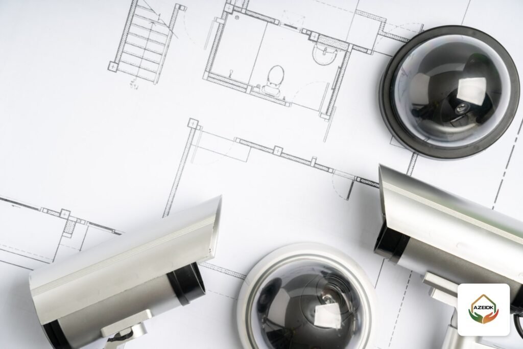
A CCTV layout plan is the drawing that shows, on the building floor plan, where each camera goes, which type and lens it uses, which way its field of view points, and how its cable runs to the switch and the recording room. You read it from the legend on the same sheet, because CCTV symbols differ from one design office to another. On Saudi projects the layout plan is normally submitted with a riser diagram and a camera schedule so the consultant can review it before installation.
Key takeaways
- A CCTV layout plan answers four questions: where the camera is, what it sees, how it gets power and network, and where the video is recorded.
- Do not rely on the symbol shape alone. The sheet legend is the reference for reading any CCTV symbol.
- An international symbol reference exists: AG-01 from the Security Industry Association (SIA), with symbol files in formats that include AutoCAD and DWG.
- Copper cable from switch to camera is limited to a 100 m channel under structured cabling standards, and the plan should show this.
- The field of view drawn on the plan must come from the datasheet of the actual lens, not from a rough sketch.
In this article
- What is a CCTV layout plan and what goes on it?
- CCTV drawing symbols: how to read them
- What a CCTV shop drawing must show
- Layout plan, riser or CCTV diagram?
- CCTV drawing software: AutoCAD and DWG blocks
- How to prepare a CCTV layout plan, step by step
- Common mistakes on CCTV drawings
- Frequently asked questions
- Conclusion
What is a CCTV layout plan and what goes on it?
The layout plan is the sheet the site technician installs from, the consultant reviews, and the owner checks at handover. Dots on a floor plan are not enough. A useful plan shows:
- Camera location and tag: a fixed tag such as CAM-GF-01 that repeats in the camera schedule, the riser and the recorder programming.
- Camera type: dome, bullet, turret, PTZ or panoramic.
- Lens and field of view: focal length (for example 2.8, 4 or 6 mm) and the FOV cone drawn at the horizontal angle given in the datasheet.
- Mounting height: height changes the real distance at which faces are clear.
- Cable route and containment: conduit or cable tray from camera to switch.
- Rack and recorder location: the telecom or control room, and the switch location on each floor.
- Legend and general notes: the definition of every symbol and the installation notes.
If you are still planning coverage, start with our guide to CCTV camera placement and coverage, which explains how to set priority zones before drawing.
CCTV drawing symbols: how to read them
The question junior engineers ask most is which camera symbol is correct. In practice, CCTV symbols are not uniform across offices and contractors. Each drawing set carries its own legend, and that legend is what the consultant approves and what the plan is read from.
Internationally, the Security Industry Association (SIA), together with the International Association of Professional Security Consultants (IAPSC), publishes AG-01, an architectural graphics standard for security system layout. According to SIA, it covers categories including video surveillance, access control, intrusion sensors, doors and barriers, communications and power supplies. SIA states that version 3.1 works with Visio, AutoCAD, PDF and DWG layers, and it is sold through the SIA store. It is a voluntary reference that a designer may adopt, not a legal requirement in Saudi Arabia.
The table below shows how system elements are commonly identified in a legend and what information should sit next to each symbol. The shapes themselves follow the legend of the sheet.
| Element | How it usually appears in the legend | Information required next to the symbol |
|---|---|---|
| Fixed dome camera | Circle or camera symbol with a letter for the type | Tag, lens, indoor or outdoor |
| Bullet camera | Rectangular camera symbol with a clear direction | Tag, lens, IR range |
| PTZ camera | Camera symbol with a mark for pan/tilt | Optical zoom, mount, power source |
| Panoramic or fisheye camera | Circle with a full coverage ring | Mounting height and FOV |
| Field of view cone | Shaded sector from the camera | Horizontal angle from the datasheet and target distance |
| Network video recorder (NVR) | Rectangle marked NVR inside the rack | Channels and number of drives |
| PoE switch | Rectangle marked SW or PoE | Port count and power budget |
| Cable and containment | Dashed line or a line type per system | Cable type and conduit or tray size |
What a CCTV shop drawing must show
The design drawing sets the intent. The shop drawing is built on the real site and the approved equipment. When we prepare one, we check:
- Approved equipment: camera and lens model as in the approved submittal. Changing a lens from 4 mm to 2.8 mm changes both the angle and the distance.
- Correct FOV cone: drawn at the datasheet angle. For the Hikvision DS-2CD2T46G2-2I4I network camera, the datasheet gives a horizontal FOV of 103° for 2.8 mm, 83° for 4 mm and 53° for 6 mm.
- Cable length: ANSI/TIA-568 and ISO/IEC 11801 set a 100 m horizontal channel: 90 m permanent link plus 10 m of patch cords. A camera beyond that needs a closer switch or another solution shown on the plan.
- Power: PoE or a separate adapter, and the total load per switch. See our article on PoE switches and the CCTV power budget.
- Coordination: no clashes with lighting, diffusers, sprinklers and fire detectors in the ceiling, and cable routes coordinated with other services.
- Storage: recorder channels and drives sized from resolution, frame rate and retention. Use the CCTV storage calculator and our guide to NVR storage and bandwidth calculation.
This coordination is the core of AZEIDK’s shop drawings and coordination service, part of our security and surveillance systems solutions.
Layout plan, riser or CCTV diagram?
Three or four different sheets are often confused. Each one answers a different question:
| Sheet | What it shows | Main user |
|---|---|---|
| Layout plan | Camera positions on each floor plan, FOV and cable routes | Installer and site engineer |
| Riser diagram | Floor-to-floor links: switches on each floor, backbone fiber or cable, main rack | Network engineer and consultant |
| IP CCTV diagram | Cameras, switches, recorder, monitors and the network connection | Programming and integration engineer |
| CCTV wiring diagram | Cable terminations and power for each device | Technician during installation and maintenance |
In analog (HD over coax) systems the wiring diagram differs because each camera runs to a DVR on coaxial cable. See IP vs analog CCTV.
CCTV drawing software: AutoCAD and DWG blocks
Most Saudi project drawings are produced in AutoCAD and issued as DWG and PDF, and some large projects work in BIM models such as Revit. A CCTV symbol DWG is normally loaded as a block library. Blocks work best with attributes such as camera tag and lens, so the camera schedule can be extracted from the drawing.
A practical note: do not copy blocks from unknown files without checking them. Make sure each symbol matches the sheet legend and the FOV cone is drawn to scale. To work out the angle and recognition distance before drawing, read our CCTV installation guide.
How to prepare a CCTV layout plan, step by step
- Survey: visit the site and photograph entrances, corridors and light sources. See site technical survey for fire and CCTV systems.
- Set the goal for each zone: detect movement, recognize a person, or identify a face clearly. The goal sets the lens and distance.
- Place cameras on the plan: draw the real FOV cone and check blind spots.
- Design the network: place switches so no channel exceeds 100 m, and check the PoE budget.
- Size storage: retention, resolution and frame rate.
- Review, then submit: check clashes with other services, then submit the plan with the camera schedule and datasheets to the consultant.
For the legal side of installing cameras in facilities, see security camera law obligations in Saudi Arabia.
Common mistakes on CCTV drawings
- One fixed cone angle for every camera regardless of the lens.
- No legend, or the same symbol for dome and bullet cameras.
- No camera tags, which makes it hard to match the plan to recorder programming later.
- Ignoring cable length until the technician finds a camera more than 100 m from the switch.
- Cameras facing a strong light source such as a glass door or window without review.
- Plans not updated after installation, so the as-built set does not match the site.
Frequently asked questions
What is a CCTV layout plan?
It is the drawing that places CCTV cameras on the floor plan and shows each camera’s type, lens, field of view and cable route to the switch and recorder.
Is there one standard CCTV symbol for drawings?
No single symbol is used by every office. The sheet legend is the reference. A voluntary international standard exists: SIA AG-01.
Where can I get a CCTV symbol DWG?
SIA sells the AG-01 files, including DWG, through its store. Many offices also keep an in-house block library. The symbol must match the sheet legend.
What is the difference between a CCTV layout and a CCTV wiring diagram?
The layout shows camera positions and routes on the floor plan. The wiring diagram shows cable terminations and power for each device.
What is the maximum network cable length from switch to camera?
Structured cabling standards set a 100 m channel: 90 m permanent link plus 10 m of patch cords.
Is the layout plan enough for consultant submission?
Consultants usually also ask for the riser, the camera schedule and equipment datasheets. The final list is set by the consultant on each project.
Conclusion
A good CCTV layout plan is easy to read: symbols defined in a clear legend, tagged cameras, FOV angles taken from the datasheet, cables within the allowed length, and coordination with other services. Every hour spent on the drawing saves days of rework on site.
Need a CCTV layout plan or shop drawing for your project? The AZEIDK team prepares surveillance shop drawings and coordinates them with the other building systems. Talk to the AZEIDK team
Related guides
- Fire Alarm Brands in KSA: Who Makes What and How to Verify Each Model’s Approval
- LUYUAN Ductile Iron Grooved Fittings: Rigid and Flexible Couplings, Elbows and Tees for Sprinkler Systems
- Data Center Fire Protection Guide: Detection and Suppression
- PBX Maintenance and Common Faults: Line Outages, Voice Quality and IP Phones