
A successful fire alarm system installation is not proven by a panel that lights up on commissioning day. It is proven when every device reports with the right address, the system runs on batteries during a power cut, and the drawings and records handed over match the site.
This guide follows the installation sequence on Egyptian projects, from survey to handover. It shows what to expect at each stage if you plan to use the AZEIDK Egypt supply and installation service for Context Plus systems.
Key takeaways
- The binding reference in Egypt is the Egyptian Code for the Design and Implementation of Fire Protection for Buildings — 2026 edition (Ministerial Decree No. 355 of 2026). Part 3 covers electrical requirements, detection and alarm.
- NFPA 72 (2025 edition) is a technical reference for installation, documentation and testing. The panel manufacturer’s installation manual governs panel wiring and circuit limits.
- Containment goes in first, then cables are pulled and tested before any device is connected. Detector heads are fitted last.
- The panel needs a dedicated, clearly marked supply circuit and batteries sized for the required standby and alarm time.
- The address schedule, zone chart and panel text must match the site before acceptance.
In this article
- What governs fire alarm system installation in Egypt?
- Step 1: Site survey and shop drawings
- Step 2: Containment and cable pulling
- Step 3: Mounting field devices
- Step 4: Panel installation, power supply and batteries
- Step 5: Zone and loop wiring
- Step 6: Numbering and labelling
- Step 7: Pre-commissioning checks
- Step 8: Testing and handover
- Common mistakes in the installation sequence
- Context Plus systems from AZEIDK Egypt
- Frequently asked questions
- Conclusion
What governs fire alarm system installation in Egypt?
The legal framework starts with Egyptian Building Law No. 119 of 2008 and its executive regulations, which oblige the permit applicant to apply fire protection requirements under the Egyptian code. The current edition is the Egyptian Code for the Design and Implementation of Fire Protection for Buildings — 2026 edition, prepared by the Housing and Building National Research Center (HBRC). Its third part covers electrical requirements and detection and alarm systems. The General Directorate of Civil Protection (Ministry of Interior) reviews drawings and inspects buildings before occupancy.
Many specifications also use NFPA 72 as a technical reference, though it is not legally binding in Egypt on its own. Chapter 7 (Documentation) sets design and completion documents, Chapter 10 (Fundamentals) covers power supplies and panels, Chapters 17 (Initiating Devices) and 18 (Notification Appliances) cover device locations, and Chapter 14 covers inspection, testing and maintenance. Wiring details, circuit lengths and permitted cable types come from the panel manufacturer’s installation manual.
Step 1: Site survey and shop drawings
Before ordering materials, check the approved drawings against the site: ceiling heights, false ceilings, beams, HVAC diffusers and the proposed panel location. Then prepare shop drawings showing every zone or loop route, each numbered device, and the main and repeater panels.
At the same stage, send the submittal to the consultant: datasheets and certificates for each device, plus a statement that detectors and modules are compatible with the panel. Mark any later site change on the drawings before building it, because the as-built drawings depend on it.
- Coordinate alarm routes with HVAC, electrical and ceiling works.
- Confirm call point and sounder positions at exits.
- Define interfaces: HVAC shutdown, lifts, doors, and flow and tamper switches on the firefighting network.
Step 2: Containment and cable pulling
Install conduit or metal trunking and junction boxes first, and pull cables only when the route is complete. The basic rules: keep alarm cables separate from power cables, use metal fixings that will not collapse early in a fire, run the outgoing and return legs of an addressable loop on different routes, keep joints to a minimum, and leave enough slack at each device and at the panel for termination.
The cable type (standard or enhanced fire-resistant, or listed to the US route) is set by the design, the project specification and the manufacturer’s instructions. For cable types, standards and separation, see our guide to fire alarm cables in Egypt.
Step 3: Mounting field devices
Fix detector bases, call point back boxes and sounders once heavy works in each area are finished, and number each base. Fit detector heads only after finishing and cleaning, because dust affects smoke detectors (see our guide to installation and testing mistakes).
- Detectors: at the approved positions, away from HVAC airflow, and of the type specified for each space (smoke, heat or beam).
- Manual call points: at exits and at the height set by the project’s adopted reference.
- Sounders and beacons: at the design positions that deliver the required sound and light levels.
- Input/output modules: next to the equipment they monitor or control, within reach for maintenance.
For call point positions, mounting heights and sound levels, see our guide to manual call points and sounders.
Step 4: Panel installation, power supply and batteries
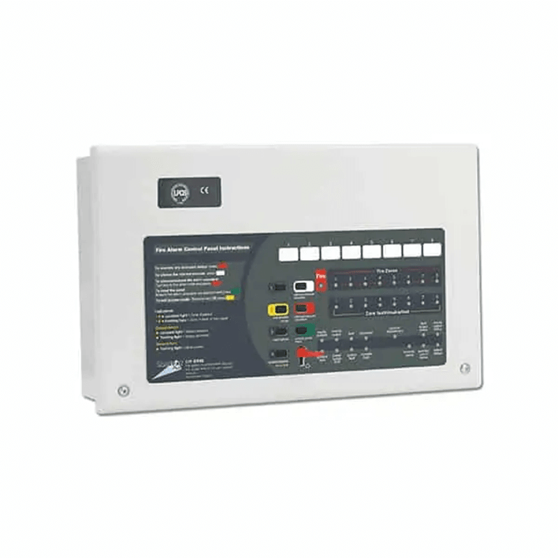
Install the panel at the approved location, usually a dry, supervised area the emergency team can reach easily. Fix it to a flat wall, bring cables in through the cabinet knockouts, and leave clear space in front.
Primary power
Official inspection checklists based on NFPA 72, such as the El Reno Fire Department checklist built on the 2016 edition, call for the panel to be fed from a dedicated branch circuit. The breaker is red and identified as a fire alarm circuit, protected against accidental switching off with a lock, and its location is permanently recorded inside the panel. Check them against the edition in the project specification and the Egyptian code.
Batteries (secondary power)
According to industry references on NFPA 72, secondary power for a non-voice system must run it for 24 hours in standby, followed by 5 minutes of general alarm. Voice evacuation systems use a different alarm duration, so take the values from the edition adopted for the project. Battery size comes from the standby and alarm current of the panel and all devices, and many designers add a margin of about 20% for ageing. This is common practice, not a requirement. Batteries are marked with their month and year of manufacture and are connected only after mains power, following the start-up order in the manufacturer’s manual.
Step 5: Zone and loop wiring
Wiring follows the manufacturer’s manual for each system type:
| Item | Conventional system | Addressable system |
|---|---|---|
| Circuit layout | One zone per part of the building, with detectors and call points wired to it | A loop that leaves the panel and returns to it, with an individual address for each device |
| End of circuit | The end-of-line (EOL) device specified by the manufacturer at the last device | The loop returns to the panel’s return terminals |
| Alarm location | By zone | By device, with a text description |
| What to check in the manual | Devices per zone, EOL value and sounder circuits | Devices and isolators per loop, maximum loop length and resistance, and addressing method |
Terminate conductors firmly with the correct polarity, dress the wiring so each circuit can be traced, and set device addresses to the approved schedule before powering the loop. For choosing between the two system types, see our guide to conventional and addressable fire alarm systems.
Step 6: Numbering and labelling
The emergency team must read the exact alarm location from the panel display. Link each address or zone to a clear location (floor and room or corridor), and program the panel text with the names used on site.
- Number cables at both ends and at junction boxes.
- Label every device with its number or address.
- Fix a zone chart next to the panel.
- Name every control output clearly in the panel.
Step 7: Pre-commissioning checks
Before devices are connected and the panel is powered, test the cables: continuity, no short circuits or earth faults, no stray voltage, and loop resistance. Disconnect devices before any high-voltage insulation test. Record results per circuit against the panel manual limits. The cable guide linked above explains these tests.
Then power the panel from the mains, connect the batteries, and confirm that every expected device appears on each loop with no duplicate or missing addresses, and no faults, before functional testing.
Step 8: Testing and handover
Functional tests cover every detector and call point (with the correct text), the notification appliances, control outputs against the cause and effect matrix, simulated faults such as a removed device or open circuit, and transfer to batteries on mains failure.
| Stage | What is handed over or recorded |
|---|---|
| Drawings and approval | Approved shop drawings and a submittal with datasheets and certificates |
| Containment and cables | Test results for each circuit before termination |
| Panel and power | Battery calculation and details of the dedicated supply circuit |
| Wiring and programming | Address and zone schedule, and a copy of the panel configuration |
| Testing | Test record for every device and control output, and battery test results |
| Handover | As-built drawings, completion documents and operator training |
NFPA 72 dedicates part of its documentation chapter to completion documentation where codes or contracts require it. A good handover file lets the owner maintain and modify the system later.
Common mistakes in the installation sequence
- Pulling cables before the containment is complete, then adding unplanned joints to make up lengths.
- Running both legs of a loop in the same trunking, so one damaged route cuts both.
- Installing the panel in an unfinished, dusty room.
- Feeding the panel from a circuit shared with other loads, or from an unmarked, unlocked breaker.
- Batteries with no capacity calculation or manufacture date.
- Unnumbered devices, or panel text that does not match the site.
- Site changes missing from the as-builts.
Context Plus systems from AZEIDK Egypt
As part of its fire detection and alarm solutions, AZEIDK Egypt supplies and installs Context Plus systems. Context Plus, a British fire alarm manufacturer since 1984, offers ZFP addressable panels, CFP and FP conventional panels, Series 65A smoke and heat detectors, 55000-268 reflective beam detectors, and manual call points, sounders, beacons and input/output modules. Approvals vary by model (EN 54 conformity, or UL listing for specific models), so check each model’s datasheet.
Frequently asked questions
When are detector heads fitted during installation?
Bases go in with the electrical works; heads go in after finishing and cleaning, so dust does not affect smoke detectors.
How long must fire alarm panel batteries last?
According to industry references on NFPA 72, a non-voice system needs 24 hours in standby followed by 5 minutes of general alarm, unless the approved project documents require otherwise. Voice evacuation systems use a different duration. Size them from the current draw of the panel and all devices, with a safety margin.
Is testing one device per zone enough before handover?
No. Test and record every device and control output. One wrong address or text can mislead the emergency team.
Where do loop length and device limits come from?
From the manufacturer’s installation manual and datasheet for the panel used. They vary by panel and by cable.
What documents should the owner receive after installation?
As-built drawings, the address schedule, the panel configuration, the battery calculation, test records and datasheets, plus operator training.
Conclusion
Fire alarm system installation is a chain of stages: drawings that match the site, tested cables, numbered devices, a panel with a dedicated supply and sized batteries, and programming that matches the approved schedule. Follow this order and document each stage, and final testing confirms the work instead of becoming a fault hunt.
Planning the supply and installation of a fire alarm system? Send us your drawings and BOQ, and we will propose Context Plus panels and devices with an installation and testing plan. Talk to the AZEIDK Egypt team