
An automatic sprinkler system attacks a fire where it starts, in its first minutes, before the fire brigade arrives and without anyone touching it. It only works if it is designed on the right hazard classification and approved hydraulic calculations, built with listed or approved components, and tested before handover.
Below: system types and components, NFPA 13 design basics, Egyptian approval, submittals, acceptance tests and common mistakes.
Key takeaways
- Sprinklers open one by one from heat: only a head heated to its rating opens. Deluge systems, with open heads, are the exception.
- Wet pipe systems are the most common where there is no freezing risk. Dry, pre-action and deluge systems have specific uses.
- Design starts with hazard classification under NFPA 13 (2025 edition), then design density, design area and hydraulic calculations.
- In Egypt the binding reference is the Egyptian fire protection code (2026 edition), with design and installation approved by civil protection.
- Under NFPA 13, a new system is hydrostatically tested at 200 psi (about 13.8 bar) for two hours with no pressure loss.
In this article
- Types of automatic sprinkler systems
- Main components of a sprinkler system
- Hazard classification: where design starts
- Sprinkler system design basics
- The Egyptian code and civil protection approval
- Submittals before installation
- Acceptance tests under NFPA 13
- Common mistakes in sprinkler systems
- System components available from AZEIDK Egypt
- Frequently asked questions
- Conclusion
Types of automatic sprinkler systems
All types differ in what the pipes hold in normal conditions and how water flow starts.
| System | Pipes in normal conditions | How it operates | Typical uses |
|---|---|---|---|
| Wet pipe | Water under pressure | A head opens from heat and water discharges at once | Offices, hotels, hospitals, shops, residential buildings |
| Dry pipe | Air or nitrogen under pressure | A head opens, air pressure drops, the dry pipe valve trips and water follows after a short delay | Unheated areas at risk of freezing, such as freezer rooms and loading areas |
| Pre-action | No water | A separate detection system must open the valve first; heads then operate from heat | Server rooms, data centres, libraries, museums |
| Deluge | Dry, open heads | A detection signal opens the deluge valve and all heads discharge together | Fast-spreading hazards such as some chemical stores, aircraft hangars and power plants |
Most buildings in Egypt face no freezing risk, so wet systems dominate: they are simple and fast. Where accidental discharge is a concern, such as server rooms, the designer may choose pre-action or gas suppression; see our clean agent suppression guide.
Main components of a sprinkler system
Sprinkler heads
A sprinkler is a small valve held shut by a heat-sensitive element, usually a liquid-filled glass bulb that bursts when heated. Heads are classified by:
- Response: standard response heads usually have a 5 mm bulb, quick response heads a 3 mm bulb. The difference is measured by the response time index (RTI). Since 1996, NFPA 13 has required quick response sprinklers in new light hazard systems.
- Orientation: upright, pendent, sidewall or concealed. Each head is installed only in its listed orientation.
- Temperature rating: chosen from the highest expected ceiling temperature and shown by the bulb colour.
| Bulb colour | Rating (°C) | Rating (°F) |
|---|---|---|
| Orange | 57 | 135 |
| Red | 68 | 155 |
| Yellow | 79 | 175 |
| Green | 93 | 200 |
| Blue | 141 | 286 |
These values are from one major manufacturer’s datasheet (Tyco TFP356), shown as an example; always check the actual model’s datasheet. Each head also has a K-factor: flow equals K times the square root of pressure.
Pipework and hangers
Systems are usually steel pipe with threaded, grooved or welded joints, or other listed materials where the standard allows. Pipe sizes come from the hydraulic calculations; hangers must comply with the standard.
Alarm valve station
Each wet system starts at an alarm check valve: a check valve with trim including pressure gauges, a main drain and a pressure switch or water motor gong that signals water flow.
Control valves and supervisory switches
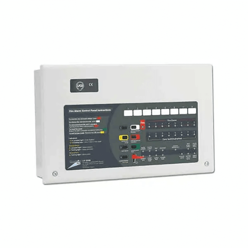
The supply is isolated by an OS&Y gate valve, whose rising stem shows its position, or an indicating butterfly valve. NFPA 13 requires control valves to be supervised open, usually by a tamper switch wired to the fire alarm panel. Each floor or zone gets a flow switch with a test and drain valve, so the panel shows where water is flowing. Our fire valves guide covers these valves in detail.
Fire department connection and water supply
The fire department connection (FDC, or Siamese connection) lets fire engines pump into the system through a check valve. The main supply is usually a fire water tank and a fire pump set designed to NFPA 20; our fire pump selection article explains how flow and pressure are set.
Hazard classification: where design starts
NFPA 13 classifies non-storage spaces by the quantity and combustibility of their contents, not by building use category. The design engineer classifies each space.
| Classification | Short description per NFPA 13 |
|---|---|
| Light hazard | Low quantity and combustibility of contents |
| Ordinary hazard, Group 1 | More contents, low combustibility; stockpiles up to about 2.4 m (8 ft) |
| Ordinary hazard, Group 2 | Higher quantity and combustibility; stockpiles up to about 3.7 m (12 ft), or 2.4 m for higher heat release contents |
| Extra hazard, Group 1 | Very high combustible quantities, including dust and lint areas where fire spreads fast |
| Extra hazard, Group 2 | Very high quantities plus substantial flammable or combustible liquids, or extensive shielding |
High-piled and rack storage has its own NFPA 13 chapters and criteria; see our warehouse fire protection guide.
Sprinkler system design basics
Design density and design area
In the density/area method, the designer applies a discharge density (mm/min or gpm/ft²) over a design area called the remote area, the hydraulically most demanding part of the system. NFPA 13 links density and area to hazard class and adds hose allowances and a water supply duration. Take values from the adopted edition, not another project.
Hydraulic calculations
Calculations run from the most remote sprinkler back to the source, using the Hazen-Williams formula for friction loss plus elevation changes. The resulting flow and pressure are checked against the pump or network supply curve. A 2025 change: dry systems using vapour corrosion inhibitors or negative pressure systems may use a C-factor of 120 if installed and maintained to the manufacturer’s instructions.
Spacing and coverage
Maximum coverage per head, spacing and distance from walls depend on hazard class, sprinkler type and listing. Obstructions such as beams, ducts and cable trays must be checked. The 2025 edition added requirements for ceilings above 30 ft (about 9 m).
The Egyptian code and civil protection approval
Egyptian Building Law No. 119 of 2008 and its executive regulations require permit applicants to apply fire protection requirements under the Egyptian code. The current edition is the Egyptian Code for the Design and Implementation of Fire Protection for Buildings — 2026 edition (Ministerial Decree No. 355 of 2026), prepared by the Housing and Building National Research Center (HBRC). Its second part covers mechanical firefighting systems.
The General Directorate of Civil Protection (Ministry of Interior), through governorate departments, reviews fire protection drawings and systems and inspects buildings before occupancy. NFPA 13 is a technical reference used where the code adopts it or the contract requires it; it is not legally binding in Egypt on its own. See our article on fire protection requirements in Egypt.
Submittals before installation
The consultant usually asks for a submittal package with:
- Shop drawings: pipe routes and sizes, head and valve locations, hangers.
- Hydraulic calculations for the remote area, with the supply curve.
- Datasheets for heads, valves, flow and tamper switches, pipes and fittings.
- Proof of listing or approval, checked in the UL or FM Approvals directory against the exact model number.
- Consultant material approval, then civil protection approval of drawings per the project procedure.
Acceptance tests under NFPA 13
- Flushing: underground supply mains are flushed until the water runs clear before connection to the overhead system, per NFPA 24, which NFPA 13 refers to.
- Hydrostatic test: 200 psi (about 13.8 bar) for two hours with no loss; parts normally above 150 psi are tested at 50 psi above working pressure. Loss means a gauge drop or visible leakage.
- Dry systems: an additional air leakage test and a dry pipe valve trip test.
- Operational tests: alarm test from the inspector’s test valve, flow and tamper signals checked at the panel, and a main drain test with pressures recorded.
- Certificate: the Contractor’s Material and Test Certificate, signed by contractor and consultant.
After handover, NFPA 25 (2026 edition) is the technical reference for inspection, testing and maintenance, alongside manufacturer and authority requirements.
Common mistakes in sprinkler systems
- Copying pipe sizes from a similar project without calculations for this one.
- Classifying a space by its name, not its contents, especially storage rooms in commercial buildings.
- Installing a head in an unlisted orientation, or mixing quick and standard response heads without checking the standard.
- Ignoring obstructions added later by HVAC and electrical works.
- Leaving a control valve closed after maintenance with no supervision to flag it.
- Accepting components without checking the actual model in the UL or FM directory.
System components available from AZEIDK Egypt
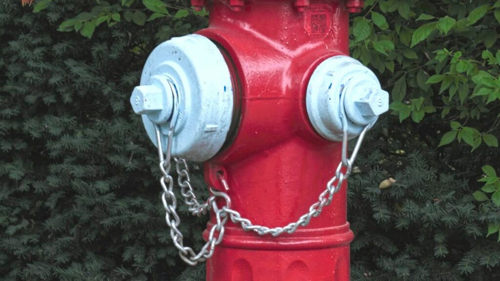
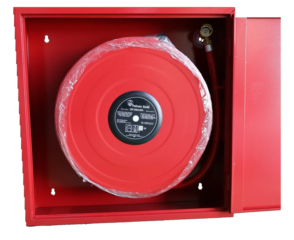
AZEIDK Egypt’s fire-fighting systems range covers sprinkler system components, hydrants, fire hose cabinets, valves, fire mains and HDPE pipes. From American Fire Control we supply A-3000 and AG-3000 OS&Y gate valves and the ACV-300 wet alarm check valve, plus butterfly and check valves. UL-listed or FM-approved products are available depending on the model; check each model’s datasheet for its approvals.
Frequently asked questions
Do all sprinklers go off together in a fire?
No. In wet, dry and pre-action systems each head opens only when heated to its rating, so usually only a few heads operate. Deluge systems are the exception.
Which sprinkler system type suits buildings in Egypt?
Wet systems are the most common, since most buildings face no freezing risk. The designer may choose dry systems for freezer rooms, or pre-action for water-sensitive spaces.
Quick response or standard response: what is the difference?
Quick response heads operate faster because their heat-sensitive element is smaller, and are mainly used in light hazard spaces such as offices. Standard response heads are common in higher-hazard industrial spaces.
Is NFPA 13 legally binding in Egypt?
The binding reference is the Egyptian fire protection code (2026 edition) and civil protection requirements. NFPA 13 is a technical reference for details the design adopts or the contract requires.
What is the hydrostatic test pressure for a new sprinkler system?
Under NFPA 13: 200 psi (about 13.8 bar) for two hours with no loss, or 50 psi above working pressure where working pressure exceeds 150 psi.
Conclusion
A sound sprinkler system needs correct hazard classification, hydraulic calculations linking the remote area to the supply, components checked by model, and careful installation. Civil protection approval and documented acceptance tests prove it.
Do you have a sprinkler BOQ or approved drawings? Send them over and we will go through the valves and components you need, with the datasheet for each model. Talk to the AZEIDK Egypt team