
A well-selected fire pump can still miss its rated performance if it sits in the wrong room. An elbow too close to the suction flange, a diesel room without enough combustion air, or a test header that cannot be used will show up at acceptance testing, or during a fire. That is why the fire pump room has to be designed as one system with the pumps themselves.
This guide covers room equipment, access, ventilation, piping, the test header, controllers and diesel requirements, quoting NFPA 20 (2025 edition) as a technical reference.
Key takeaways
- In Egypt, the Egyptian fire code (2026 edition) and Civil Protection approval are binding; NFPA 20 is the technical reference.
- NFPA 20 requires a fire-rated pump room with access from outside or through a protected passageway.
- The suction line is the most sensitive part: eccentric reducer, straight pipe before the flange, OS&Y gate valve rather than a nearby butterfly valve.
- Design the test header and flow meter from day one for testing at 100% and 150% of rated flow.
- A diesel room needs a correctly sized fuel tank, combustion and cooling air, and a safe exhaust.
In this article
- What is inside a fire pump room?
- Legal and technical references in Egypt
- Location, separation and access
- Ventilation, heating, drainage and lighting
- Equipment layout and service clearances
- Suction piping: the most sensitive part
- Discharge piping, test header and flow meter
- Controllers and power supply
- Diesel pump: fuel, exhaust and batteries
- Designing the room for testing
- Common fire pump room mistakes
- 3PUMP sets from AZEIDK Egypt
- Frequently asked questions
- Conclusion
What is inside a fire pump room?
A typical room houses an electric main pump, a diesel standby pump and a jockey pump, plus the pipes, valves and devices around them:
| Component | Function | Installation note |
|---|---|---|
| Suction OS&Y gate valve | Isolates the pump from the water source for maintenance | Preferred on suction; does not disturb flow |
| Discharge check valve | Stops backflow into the pump | Installed between the pump and the discharge control valve |
| Discharge control valve | Isolates the pump from the system | Indicating valve listed for fire service |
| Test header and flow meter | Measure pump performance at different flows | Connected between the check valve and the discharge control valve |
| Circulation (casing) relief valve | Prevents the pump overheating when running at no flow | Discharges to a visible drain |
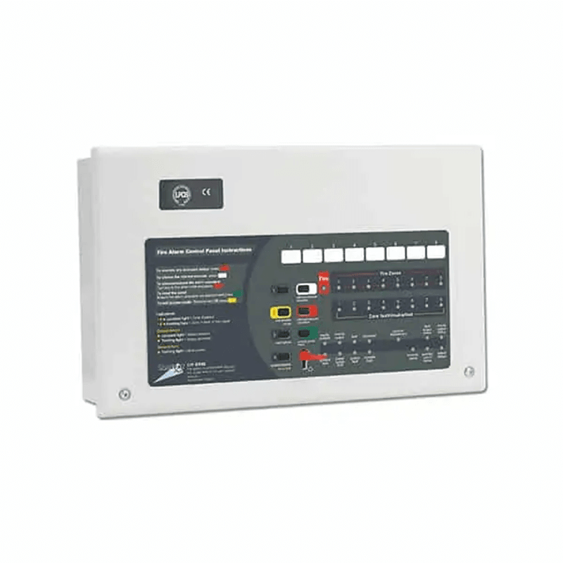
| Fire pump controllers | Automatic and manual start, monitoring | One listed controller per pump, located close to it |
| Diesel fuel tank, exhaust and batteries | Run the engine without mains power | Per NFPA 20 and the engine manufacturer’s instructions |
Legal and technical references in Egypt
The legally binding reference is the Egyptian Code for the Design and Implementation of Fire Protection for Buildings — 2026 edition (Ministerial Decree No. 355 of 2026), issued under Egyptian Building Law No. 119 of 2008. Part 2 covers mechanical systems and Part 3 electrical requirements. The General Directorate of Civil Protection (Ministry of Interior) reviews drawings and inspects before occupancy.
NFPA 20 (Standard for the Installation of Stationary Pumps for Fire Protection) is widely used in the region as the technical reference for pump room details. It applies where the designer or contract adopts it and does not replace the Egyptian code.
Location, separation and access
NFPA 20 treats the pump room as a space that must stay usable during a fire, so it requires a fire-rated separation. Its tables set the rating by building type: typically 2 hours, with 1 hour allowed in some fully sprinklered buildings that are not high-rise, or separation by distance for a detached pump house.
Access must be pre-planned with the fire service: directly from outside, or through a passageway with the same fire rating as the room. Good practice is a ground-floor room on an external wall, with doors big enough for the largest equipment. The room is not a store for anything that does not serve the pumps.
Ventilation, heating, drainage and lighting
Heating and room temperature
NFPA 20 requires electric pump rooms to be kept above about 4°C (40°F) so water-filled piping does not freeze. In diesel rooms, the temperature must not drop below the minimum recommended by the engine manufacturer. In Egypt, summer heat is the bigger issue: keep the room within the datasheet limits of engines and controllers.
Ventilation
The standard requires pump room ventilation. In a diesel room it is a calculation: combustion air, radiator cooling air where used, and removal of engine and exhaust heat, using the quantities in the engine installation manual.
Drainage and lighting
Slope the floor away from the pump, driver and controller to a drain or sump sized for casing relief discharge, packing leakage and any test water. Provide normal and emergency lighting; in diesel rooms the starting batteries must not feed the emergency lights.
Equipment layout and service clearances
Start from the suction and discharge routes, then place controllers, fuel tank and exhaust:
- Clearance to open pump casings and lift parts without dismantling pipework.
- Working space in front of controllers per the Egyptian code’s electrical part.
- A concrete plinth for the set’s weight and vibration, per the manufacturer.
- A clear route for test hoses or the flow meter loop.
Suction piping: the most sensitive part
A pump only performs if water enters it evenly. NFPA 20 limits include:
- Suction valves: use a listed OS&Y gate valve. A butterfly valve is not allowed on the suction line within 50 ft (about 15 m) of the pump suction flange.
- Elbows: on horizontal split-case pumps, an elbow whose plane is parallel to the pump shaft must be at least 10 pipe diameters from the suction flange.
- Reducers: must be eccentric and installed so no air pocket forms, which normally means flat side up.
- Velocity: water velocity near the suction flange must not exceed 15 ft/s (about 4.6 m/s) at 150% of rated flow.
- Backflow preventers: if fitted on suction, at least 10 pipe diameters from the flange.
To select the duty point and check suction conditions first, see our fire pump selection guide.
Discharge piping, test header and flow meter
The usual discharge arrangement is pump, then check valve, then control valve. Discharge components must withstand the highest possible pressure: churn (no-flow) pressure plus the maximum suction pressure. NFPA 20 permits a main pressure relief valve only with diesel drivers or variable speed pressure limiting controllers, never as a substitute for properly rated components.
The test header is a set of 2½-inch hose outlets; flow is measured at the hose nozzles with a Pitot gauge. It connects between the check valve and the control valve, on an external wall or outside the room, so test water does not flood the space. A table in NFPA 20 sets header size and outlet count by pump flow. A closed-loop flow meter that returns water to the tank needs an alternative measuring device in series to verify it.
Common practice is a separate pressure sensing line from the discharge for each controller, routed and fitted as the controller’s installation manual specifies.
Controllers and power supply
A fire pump controller must be listed for fire pump service. It sits as close as practical to its driver, in an enclosure suited to the room and protected from water spray, and is never used as a junction box for other equipment.
The electrical engineer sets the source, route and protection of the pump supply under the electrical part of the Egyptian code, using NFPA 20 and NFPA 70 as guidance. Power must stay available during a fire; protective devices must not trip it like an ordinary circuit.
Diesel pump: fuel, exhaust and batteries
- Fuel tank: since the 2022 edition, NFPA 20 sizes the minimum tank from the engine’s fuel consumption at rated power for 12 hours, plus 5% for sump and 5% for expansion. If consumption is unknown, use the older method: 1 gallon per horsepower plus the same allowances.
- Fuel level: keep the tank full and never below two-thirds, with a level gauge and a dedicated fill and vent.
- Exhaust: route it safely outside, size it to keep back pressure within the engine limit, and insulate it.
- Starting: NFPA 20 requires two independent starting sources, which the controller alternates between.
Designing the room for testing
The site acceptance test measures pump performance at churn, 100% and 150% of rated flow, and checks automatic and manual starting. At design stage, check where test water will go, that there is room for the header hoses, that suction and discharge gauges are fitted, and that pump speed can be measured. NFPA 25 (2026 edition) then gives periodic testing guidance. For the full test procedure, see our fire pump testing guide.
Common fire pump room mistakes
- An elbow or tee right at the suction flange, or a concentric reducer that traps air.
- A butterfly valve on the suction line close to the pump.
- A test header inside the room with nowhere for the water to go.
- A diesel room short of combustion air that overheats on a long run.
- A fuel tank sized by guesswork, or an exhaust with too many bends.
- Controllers far from the pumps or exposed to water spray.
- Using the room as a store, or blocking access from outside.
3PUMP sets from AZEIDK Egypt
AZEIDK Egypt supplies complete 3PUMP fire pump sets: electric main, diesel standby and jockey pumps with controllers on a common base. Duty points currently available in Egypt are Non-UL (non-listed): 500 GPM at 8 bar, 750 GPM at 9 bar, 1000 GPM at 10 bar, 1500 GPM at 10 bar and 1500 GPM at 12 bar. UL-listed or FM-approved versions are manufactured and supplied on request. Our fire pump systems page shows the full solution.
Frequently asked questions
Does the fire pump room have to be on the ground floor?
NFPA 20 sets no particular floor, but requires access pre-planned with the fire service, from outside or through a protected passageway. A ground-floor room on an external wall is usually simplest; the final decision rests with the designer and Civil Protection.
Why not use a butterfly valve on the suction line?
Its disc stays in the waterway and disturbs flow just before the pump, so NFPA 20 prohibits it within 50 ft of the suction flange. Use an OS&Y gate valve.
How is the diesel fuel tank sized?
Under NFPA 20 since the 2022 edition: the engine’s consumption at rated power for 12 hours, plus 5% for sump and 5% for expansion. Take the consumption rate from the engine datasheet.
Does a packaged set on a common base remove the need to design the room?
No. It saves some internal connections, but piping, ventilation, drainage, exhaust and clearances are still designed for each room.
Conclusion
The fire pump room is part of the pump’s performance, not just a place to put it. Separation, ventilation, drainage, the suction line, the test header, controllers and diesel fuel and exhaust are all decided at design stage. Agreeing them with the consultant and Civil Protection early avoids costly changes at acceptance.
Designing a pump room for a new project? Send us the room layout and duty point, and we will recommend a pump set with its datasheet and installation manual. Talk to the AZEIDK Egypt team