
Kitchen fire suppression system installation starts long before the cylinder reaches site. The system is designed for one hood and one set of appliances in fixed positions. Change any of these and the nozzle layout, pipe calculation and detector positions change too.
This article follows the installation and acceptance of a HoodSafer HS series system, based on the manufacturer’s installation manual in the material submittal published by AZEIDK Egypt. For components, operating principle and maintenance in general, see our commercial kitchen fire suppression guide.
Key takeaways
- The HoodSafer manual defines three nozzle types (H1, H2 and H3) with clear placement rules.
- Each model (HS4, HS8 and HS16) has a maximum discharge line length. Elbows and tees are deducted from it as equivalent lengths.
- The system will not work until the detection line is tensioned and the installation safety device is removed from the actuation mechanism.
- Acceptance covers a leak test, microswitch and gas valve checks, labels, staff training and handover documents.
In this article
- The reference framework: law, standards and manufacturer instructions
- Stage 1: site survey before design
- Stage 2: nozzle layout and flow point calculation
- Stage 3: cylinder and discharge piping
- Stage 4: detection line, manual pull station and gas valve
- Stage 5: testing, acceptance and handover
- Common mistakes in kitchen system installation and acceptance
- Frequently asked questions
- Conclusion
The reference framework: law, standards and manufacturer instructions
In Egypt, the binding reference is the Egyptian Code for the Design and Implementation of Fire Protection for Buildings — 2026 edition (Ministerial Decree No. 355 of 2026). Drawings and pre-occupancy inspection are handled by the General Directorate of Civil Protection (Ministry of Interior).
International standards are technical references, not a substitute for the Egyptian requirement: NFPA 17A (2024 edition) for wet chemical systems, NFPA 96 for ventilation control and fire protection of commercial cooking operations, and EN 17446 for commercial kitchen fire suppression systems. UL 300 is a fire test standard for pre-engineered units. It does not contain installation rules.
The third layer is the manufacturer’s manual, which governs installation details. The AZEIDK Egypt kitchen fire suppression page states that HoodSafer holds EN 17446:2021 certification and BSI Kitemark KM 767382, and is approved by the General Directorate of Civil Protection in Egypt. This is the manufacturer’s certificate, not AZEIDK’s; the BSI directory lists it under HoodSafer (Turkey) against BS EN 17446:2021+A1:2024.
Stage 1: site survey before design
The survey is the basis for every calculation in a kitchen fire suppression system installation. Do it after final appliance positions are fixed. Record:
- Hood: length and width, whether it is divided into sections, and the filter type (straight or V-bank) and height.
- Exhaust duct: number of duct openings and their shape (round or rectangular) and size.
- Appliances: type (fryer, grill, range top, griddle, ground stove, wok), surface size, height and position.
- Energy supply: gas line route and size, gas valve location, and electric appliances to isolate.
- Cylinder and pull station: a solid wall away from heat, on an accessible route.
The manual requires a review whenever appliances or their layout change. Write this into the handover record.
Stage 2: nozzle layout and flow point calculation
HoodSafer sizing is based on flow points. Each nozzle uses one or two flow points, and the total must not exceed the model capacity: 4, 8 or 16 flow points. Every hood section and every appliance must be covered.
| Nozzle type | Flow points | Spray angle | Use per manufacturer’s manual |
|---|---|---|---|
| H1 (one marked line) | 1 | 40–60° | Duct and filters (plenum behind the filters), grills, ground stoves |
| H2 (two marked lines) | 2 | 20–35° | Deep fat fryers, bratt pans and vegetable oil appliances |
| H3 (three marked lines) | 1 | 70–90° | Range tops and grill plates |
Placement rules in the manual include:
- One H1 nozzle per round duct up to 40 cm diameter, two up to 60 cm, always aimed at the centre of the duct opening.
- Filter nozzles aim at the centre of the plenum. One H1 nozzle covers a hood up to 3 m. Longer hoods need one nozzle per 2 m of length; the manual’s examples are two nozzles for a 4 m or 5 m hood and three for a 6 m hood.
- A divided hood needs a nozzle for each section.
- Appliance nozzles go over the centre of the cooking surface, within the manual’s height limits.
If the total exceeds the largest model, the manual allows two mechanically linked systems: the smaller for the hood and duct, the larger for the appliances. The detection line and gas valve connect to the larger one, which triggers the other.
Stage 3: cylinder and discharge piping
Mounting the cylinder
The manual requires the cylinder bracket to be fixed to a solid, flat surface with at least four screws, and at least 1 m from the hood. A charged cylinder can discharge violently if mishandled. The gauge must read in the green zone; the nitrogen charge is 15 bar at 21°C.
Discharge line
- Pipe and fittings in AISI 304 or 304L stainless steel, SCH40, 3/8 inch.
- No galvanised pipe or fittings. Do not bend or paint the pipe.
- Use chemical thread sealant, not PTFE tape.
- Fix with metal clamps every 1 m inside the hood and every 1.5 m outside it.
Because the gas charge is limited, each model has a maximum line length, with fittings deducted as equivalent lengths:
| Item | Value in manufacturer’s manual |
|---|---|
| Maximum equivalent straight length: HS4 | 8 m |
| Maximum equivalent straight length: HS8 | 16 m |
| Maximum equivalent straight length: HS16 | 24 m |
| Equivalent length of a 3/8 inch elbow | 0.4 m |
| Equivalent length of a passing tee / corner tee | 0.24 m / 0.82 m |
| If a fryer is the first appliance on the line | At least 3 m of pipe from the cylinder, with a minimum of 3 elbows and 1 corner tee to prevent oil splash |
Vertical limits: 150 cm maximum from the mechanism to the hood line, and 60 cm from the appliance line to the hood line.
Stage 4: detection line, manual pull station and gas valve
Detection line and heat detectors
The system uses glass heat detectors (thermobulbs) held on a tensioned stainless steel wire. When a bulb bursts, the tension releases and the mechanism operates. The manual lists three ratings: 141°C for appliances without open flame, 182°C for fryers, range tops and woks, and 260°C for open-flame grills and barbecues. Installation rules include:
- Detectors sit in the airflow path towards the duct, above the appliance.
- Detector height between 125 and 160 cm above the highest appliance surface.
- Line length up to 40 m with up to 20 bends, and corner pulleys at hood entry and exit.
- Outside the hood, use 18 mm aluminium conduit clamped every 1 m.
Manual pull station
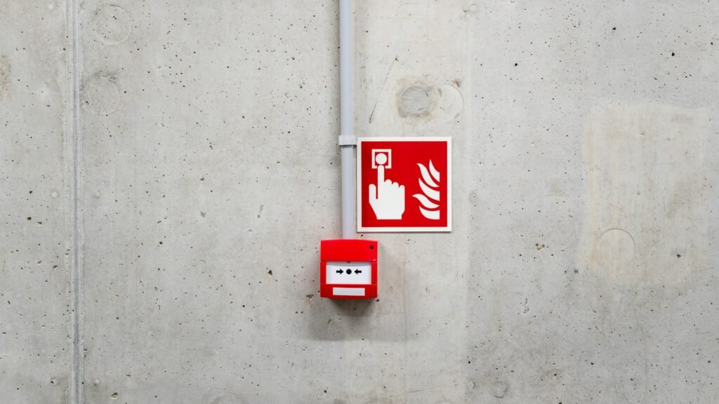
It sits at the end of the detection line, at least 140 cm above the floor and at least 2 m from the hood, in a visible and easily reached spot.
Gas shut-off valve and microswitch
The manual describes a mechanical, brass-body gas valve, 1 inch BSPP (other sizes available). It is normally closed and is held open by tensioning its wire from the actuation mechanism, so gas shuts off automatically when the system operates. The manufacturer recommends using the microswitch to stop the ventilation fans on actuation. Its contacts can also signal the alarm panel or isolate electric appliances. NFPA 96 requires fuel and electric power that produce heat in the protected appliances to shut off automatically on actuation (section 10.4.1, 2021 edition, as quoted by the Contra Costa County Fire Protection District).
Tensioning and removing the safety device
Tension the detection line only after all detectors and the pull station are installed. Tension is correct when the safety device can be removed. The manual is explicit: the system will not work while this device is in place.
Stage 5: testing, acceptance and handover
The manufacturer’s manual sets this sequence for installation and acceptance:
- Mount the cylinder, then the pull station, then the detection line, then the discharge pipework.
- Final check after nozzles and caps are fitted.
- Seal the mechanism for warranty and safety, and fit the cylinder, pull station and installation labels showing the inspection and filling dates.
- Leak test the whole system and check microswitch operation.
- Train staff on daily and weekly checks and manual actuation.
The manual does not call for an actual agent discharge at acceptance. Any functional test of the mechanism, gas valve or microswitch follows the manufacturer’s procedure only, agreed with the consultant. The manual requires installers authorised by HoodSafer, so ask for proof.
Handover file
- As-built drawings, and the flow point and equivalent length calculation.
- The test record signed by installer, consultant and owner.
- The user manual and a maintenance schedule: at least every 6 months as the manufacturer specifies, with detectors replaced every year.
- The material submittal and certificates, as explained in our guide to fire equipment technical documents.
Acceptance is not complete without a portable extinguisher for cooking oil fires (Class K, Class F in the European classification). According to Amerex, quoting NFPA 10, the maximum travel distance to it is about 9 m (30 ft), with a placard beside it telling staff to actuate the fixed system first.
Common mistakes in kitchen system installation and acceptance
- Designing before appliance positions are fixed: a moved fryer loses its nozzle coverage.
- Leaving the safety device in the mechanism: the system looks complete but will not operate.
- Wrong detector rating: a 141°C bulb over an open-flame grill can cause unwanted actuation.
- Pull station next to the hood or behind shelving.
- Gas valve downstream of some appliance branches: it must serve every appliance under the hood.
- Handover without training or labels: staff cannot find the pull station and no next inspection date is shown.
Frequently asked questions
How do I choose between HS4, HS8 and HS16?
Add up the flow points of the nozzle layout, choose the model that covers them, then check the line length limit.
Can a new cooking appliance be added after installation?
Not before a design review. It needs a nozzle, may need a detector, and may exceed the installed model.
Is HoodSafer listed to UL 300?
The certification documented on the AZEIDK Egypt page is EN 17446:2021 with BSI Kitemark. If the project specification calls for a UL 300 listing, check the manufacturer’s official documents before approval.
What is needed after handover?
Periodic maintenance at least every 6 months per the manufacturer, detector replacement every year, and a hydrostatic test or cylinder replacement every 5 years. See our maintenance and technical support services.
Conclusion
The quality of a kitchen fire suppression system installation comes down to three questions. Is every part of the hood and every appliance covered by the right nozzle? Are the discharge line and detection line within the manufacturer’s limits? And did the system leave acceptance truly ready, with the safety device removed, the gas valve connected and staff trained?
Fitting out a commercial kitchen or rearranging its appliances? Send us the hood drawing and the appliance list with positions, and we will review the right model, nozzle layout and submittal documents with you. Talk to the AZEIDK Egypt team