
The OS&Y gate valve is the most common control valve at riser bases and in fire pump rooms, because its exposed stem shows the position from a distance. But a visible stem does not stop a mistaken closure, and it does not guarantee the valve will still turn easily years later.
This article focuses on the American Fire Control (AFC) OS&Y gate valves supplied by AZEIDK Egypt: the A-3000 with flanged ends and the AG-3000 with grooved ends. It covers the datasheet, tamper switch supervision, installation and inspection. For a general comparison of valve types, see our guide to fire protection valves in Egypt.
Key takeaways
- AZEIDK Egypt lists two AFC OS&Y models: the A-3000 (flanged) and the AG-3000 (grooved), in sizes from 2.5 to 12 inches per the datasheet.
- The datasheet gives both models a maximum working pressure of 300 psi (21 bar), a maximum test pressure of 600 psi (42 bar) and compliance with AWWA C515.
- The rising stem shows the position at a glance. A supervisory (tamper) switch sends a signal to the fire alarm panel as soon as the valve moves away from fully open.
- NFPA 25 (2026 edition) sets control valve inspection frequency by supervision method: weekly, monthly or quarterly.
- The stem is much taller when the valve is open, so the design must leave enough vertical space above the valve.
In this article
- What is an OS&Y gate valve and why is it used as a control valve?
- The two AFC models: A-3000 and AG-3000
- Flanged or grooved? Selection criteria on a project
- Supervising valve position with a tamper switch
- Installation and valve orientation
- Periodic inspection and operation
- Common mistakes with OS&Y valves
- Frequently asked questions
- Conclusion
What is an OS&Y gate valve and why is it used as a control valve?
OS&Y stands for Outside Screw and Yoke: the stem thread sits outside the body, carried by a yoke above the bonnet. Turning the handwheel raises the stem and gate to open the valve. Stem up means open; stem almost out of sight means closed.
When open, the gate is fully out of the waterway, so friction loss is lower than a butterfly valve of the same size. QRFS quotes NFPA 13 (2022 edition) as requiring water supply control valves to be listed indicating valves, and a listed indicating valve must not close in less than 5 seconds. A gate valve’s slow travel meets this and limits water hammer.
The legally binding reference in Egypt is the Egyptian Code for the Design and Implementation of Fire Protection for Buildings — 2026 edition (Ministerial Decree No. 355 of 2026), whose second part covers mechanical firefighting systems, with drawings approved by the General Directorate of Civil Protection (Ministry of Interior). NFPA 13 and NFPA 25 are technical references adopted by the designer or the contract.
The two AFC models: A-3000 and AG-3000
Both are resilient wedge gate valves. The gate is ductile iron encapsulated in EPDM rubber, which seals against the body. The main difference is the end connection. The table below summarises the AFC datasheet published on the AZEIDK website:
| Item | A-3000 (flanged) | AG-3000 (grooved) |
|---|---|---|
| End connections | Flanged to ANSI B16.1 Class 125, ANSI B16.42 Class 150 or EN 1092-2 PN16 | Grooved to AWWA C606 |
| Sizes | 2.5 to 12 inches | 2.5 to 12 inches |
| Max working pressure | 300 psi (21 bar) | 300 psi (21 bar) |
| Max test pressure | 600 psi (42 bar) | 600 psi (42 bar) |
| Working temperature | 0 to 80 °C | 0 to 80 °C |
| Reference standard | AWWA C515 | AWWA C515 |
| Coating | Fusion-bonded epoxy inside and outside to AWWA C550 | Fusion-bonded epoxy inside and outside to AWWA C550 |
| Weight, 6-inch size | 62 kg | 48 kg |
Per the datasheet, the body, bonnet, yoke and handwheel are ductile iron (ASTM A536 65-45-12), the stem is 304 stainless steel the packing is PTFE graphite, and the yoke screw and handwheel nut are C95400 aluminum bronze. It also states that both models are UL listed and FM approved. The AZEIDK Egypt brand page notes that UL and FM certificates are available for specific models as shown on each datasheet, so check the exact size and end type you need in each body’s official directory. For the steps, see our guide to verifying UL and FM certifications.
Flanged or grooved? Selection criteria on a project
The end type does not decide quality. It decides how the valve joins the system:
- What the valve connects to: if the pump outlets, check valves and mains are flanged, the A-3000 makes matching easy. If the riser and branches use grooved couplings, the AG-3000 saves welding and flange work.
- Flange standard: the valve flange must match the mating pipe or equipment flange in diameter, bolt pattern and pressure class. State the standard you need in the purchase order.
- Weight and support: the flanged valve is heavier. At 6 inches the difference is about 14 kg. Allow for this in pipe supports.
- Coupling rating: with grooved ends, the couplings must also be listed for the system pressure.
- Site pressure: a 300 psi rating covers most systems, but always compare it with the highest actual pressure at the valve location, including fire pump churn pressure plus suction pressure.
Supervising valve position with a tamper switch
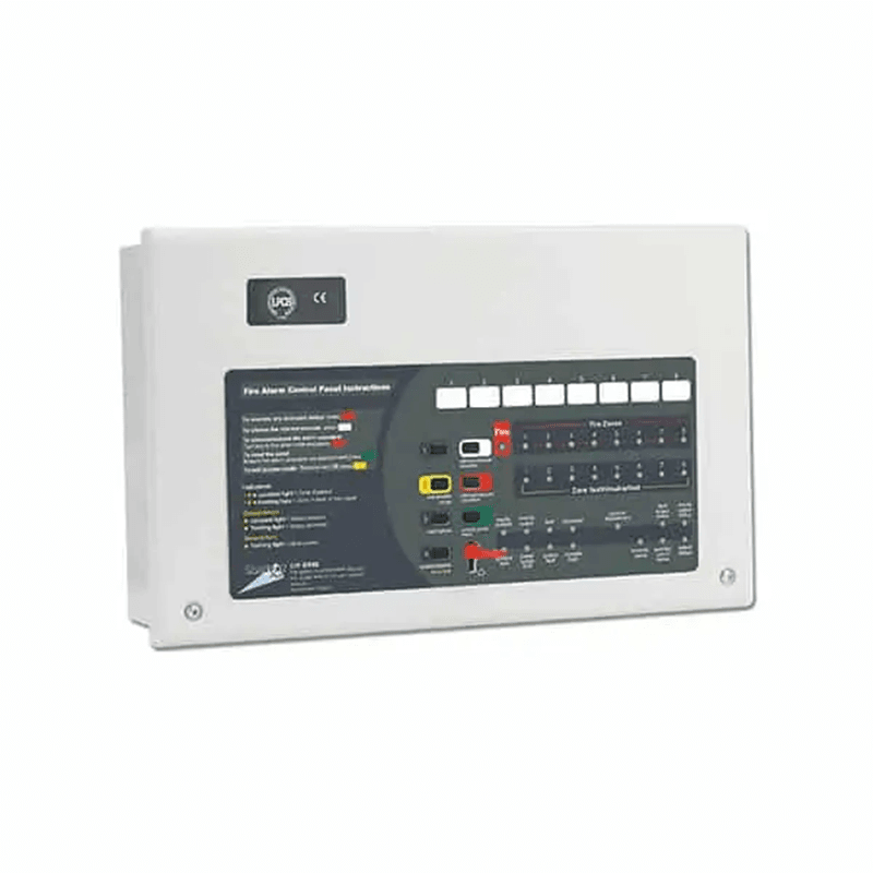
A valve closed without anyone knowing disables the sprinklers or hose cabinets it feeds. QRFS notes that mistakenly closed control valves are a leading cause of sprinkler system failure. So an OS&Y valve is fitted with a supervisory (tamper) switch on the yoke, with its arm resting on the stem. When the valve moves away from fully open, it sends a supervisory signal to the fire alarm panel. The signal clears when the valve is reopened.
Supervision methods allowed by NFPA 13
The National Fire Sprinkler Association (NFSA), quoting the 2022 edition of NFPA 13, lists four ways to supervise water supply control valves:
- A signal to a central, proprietary or remote supervising station.
- A local signal that sounds at a constantly attended location.
- Locking the valve in the correct position.
- Valves inside an owner-controlled fenced enclosure, sealed open and inspected weekly.
Project documents and the authority decide the accepted method. The switch is wired to an input on the fire alarm system and programmed as a supervisory signal, separate from a fire alarm signal.
What to check before ordering the switch
- The switch is listed for OS&Y valves and suits the stem diameter and yoke dimensions of the size you need.
- The valve stem allows the switch to be mounted as the switch maker instructs. The A-3000 and AG-3000 datasheet does not cover switch mounting, so ask the supplier to confirm it.
- The BOQ names the alarm panel interface and cable route, coordinated with the alarm contractor.
Installation and valve orientation
Vertical space for stem travel
The datasheet gives two heights for each size: closed and open. At 6 inches the valve is about 607 mm tall closed and 716 mm open. At 12 inches it is about 1,031 mm closed and 1,320 mm open. Leave room for the full open height plus the handwheel and switch, especially under low pump room ceilings and beams.
Installation orientation
The datasheet does not state an installation position for either model, although the grooved check valve in the same file is explicitly rated for horizontal or vertical installation. Some gate valve manufacturers recommend a vertical stem on horizontal pipe and a horizontal stem on vertical pipe, but this does not replace the instructions for the specific model. Ask the supplier to confirm the allowed positions before shop drawings are approved, especially if a tilted or downward stem is proposed.
Access and identification
- Locate the valve where it can be reached without temporary ladders.
- Fit a sign showing which part of the system the valve controls, as NFPA 25 requires.
- Lock or seal it open if that is the approved supervision method.
Periodic inspection and operation
The frequencies below are NFPA 25 guidance as reported by the references listed at the end of this article, for the edition each one cites. They are not an Egyptian legal requirement. Apply them with the manufacturer’s instructions and the authority’s requirements:
| Item | Action | Frequency | Reference |
|---|---|---|---|
| Valve not locked or supervised | Check position, seal, access and external leaks | Weekly | NFPA 25, 2026 edition (per QRFS) |
| Locked valve | Same check | Monthly | NFPA 25, 2026 edition (per QRFS) |
| Electrically supervised valve | Same check, plus the switch for damage | Quarterly | NFPA 25, 2026 edition (per QRFS) |
| Supervisory switch | Test that the signal is sent and clears | Semiannual | NFPA 25, 2023 edition (per NICET study guide) |
| Valve operation | Operate through full range and return to normal | Annual | NFPA 25, 2020 edition (per QRFS) |
| Stem lubrication | Grease the stem thread | Annual | NFPA 25, 2020 edition (per QRFS) |
To test the switch, close the valve slowly. Technician training material based on NFPA 25, and tamper switch makers’ installation instructions, state the signal must start within the first two handwheel turns or one-fifth of valve travel. Then reopen fully and confirm the signal clears locally and at the monitoring point.
QRFS quotes NFPA 25 (2020) as saying a fully opened valve should be backed off a quarter turn to avoid jamming. For stem packing leaks, follow the manufacturer’s instructions. For a full maintenance programme, see our article on fire system maintenance.
Common mistakes with OS&Y valves
- A valve closed for maintenance and not fully reopened, with no tamper switch.
- A tamper switch installed but never wired to the panel, or programmed as a general fault instead of a supervisory signal.
- Ordering flanged ends without naming the flange standard.
- Ignoring the open stem height under ceilings or beams.
- Painting the stem during finishing, or never greasing it.
- Accepting a UL or FM logo in a catalogue without checking the size and end type in the official directories.
Frequently asked questions
What is the difference between the A-3000 and the AG-3000?
Same sizes and pressures on the datasheet. The A-3000 is flanged; the AG-3000 is grooved to AWWA C606 and lighter.
Is the visible stem enough without a tamper switch?
The stem only helps someone who looks at it. NFPA 13 allows locking or sealing in defined cases, with more frequent inspection. Project documents and the authority decide.
Is a 300 psi rating enough for my project?
It covers most systems, but compare it with the highest pressure at the valve, including churn plus suction pressure.
How often should an OS&Y valve be inspected?
Under NFPA 25 (2026 edition), as reported by QRFS: weekly if it is not locked or supervised, monthly if locked, and quarterly if electrically supervised. It should also be operated through its full range once a year.
Can the valve be installed with a horizontal stem?
Some manufacturers recommend a vertical stem on horizontal pipe and a horizontal stem on vertical pipe. The AFC datasheet does not state a position, so confirm it with the supplier.
Conclusion
Choosing an AFC OS&Y valve starts with the end type, its standard and site pressure, then a listing check for the exact size. Design for the open stem height and specify the tamper switch and its panel connection. After handover, the valve is only as reliable as its inspection and greasing routine.
Need OS&Y valves for your project? Send us the sizes, end types, flange standard and working pressure, and we will send the datasheets for the matching AFC models. Talk to the AZEIDK Egypt team