Sprinkles
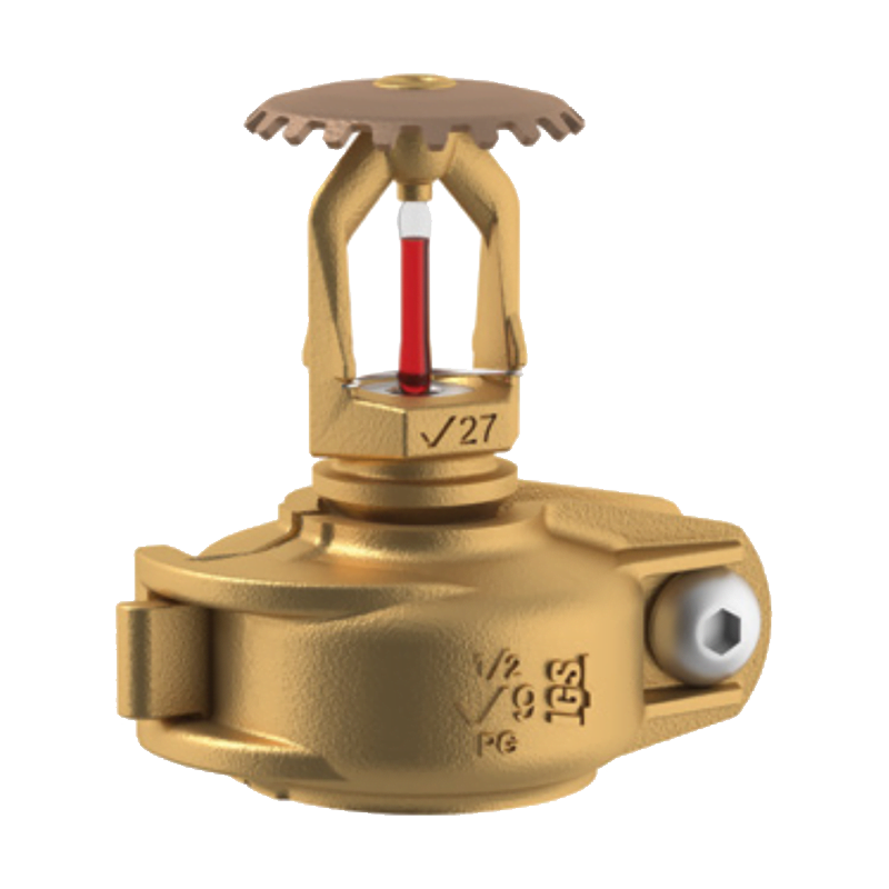
Victaulic FireLock V27 K5.6 Fire Sprinklers – V2703, V2704, V2707 and V2708
Brand
Victaulic
View Product
←
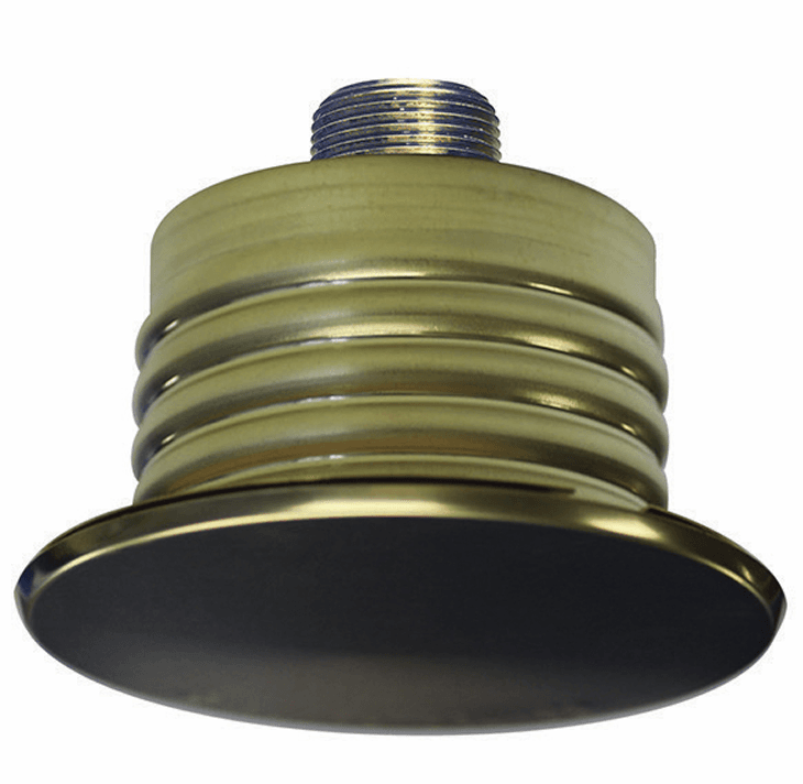
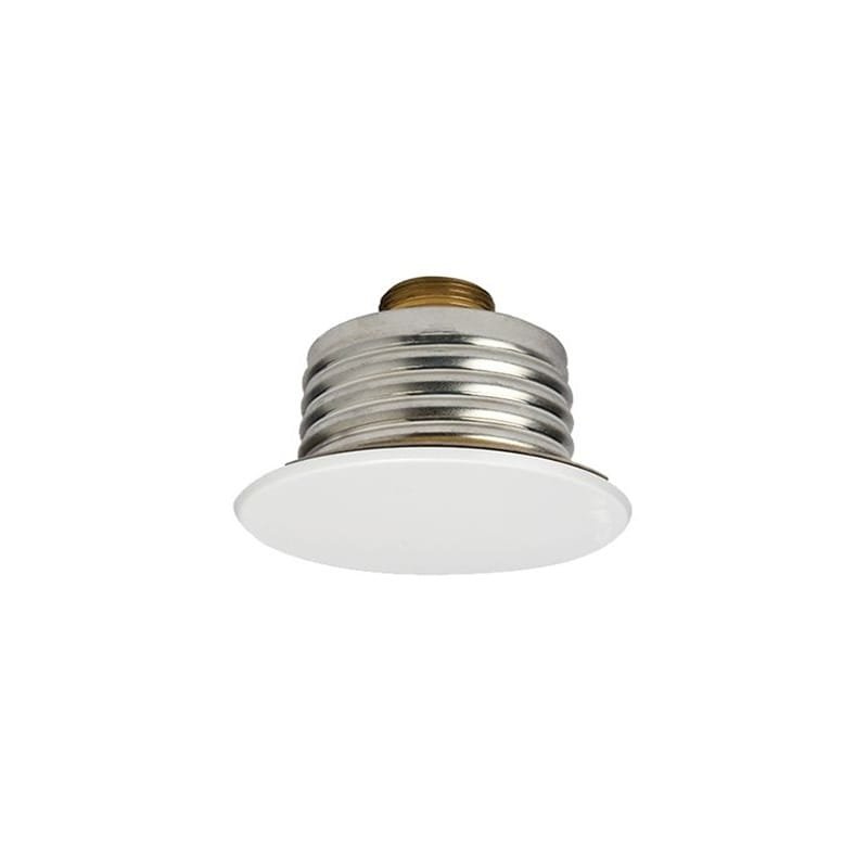
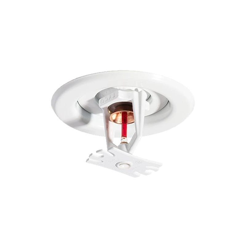
The TYCO Series RFII-MRI, SIN TY3537, is a non-magnetic concealed pendent fire sprinkler specifically designed for use inside magnetic resonance imaging rooms.
It is a quick-response, extended-coverage sprinkler for light-hazard applications and features a flat concealed cover plate that maintains a coordinated architectural ceiling appearance.
According to the non-clinical testing referenced in the technical data sheet under ASTM F2052-15, the RFII-MRI sprinkler is acceptable for use under a static magnetic field of 7 Tesla or less.
The sprinkler is intended to be ceiling-mounted inside the MR system room and close to the scanner unit. It is not intended for direct installation inside the MRI scanner or within the scanner bore.
Key Features:
• Non-magnetic fire sprinkler for MRI environments.
• Series RFII-MRI.
• Sprinkler Identification Number: TY3537.
• Concealed pendent installation.
• Quick-response operation.
• Extended-coverage performance.
• Intended for light-hazard occupancies.
• Nominal K-factor of 5.6.
• Maximum coverage up to 20 ft × 20 ft.
• Suitable for static magnetic fields up to 7 Tesla, as referenced in the data sheet.
• Flat concealed cover plate.
• Maintains a clean architectural ceiling appearance.
• 3 mm heat-sensitive glass bulb.
• Two available sprinkler temperature ratings.
• 1/2-inch vertical adjustment.
• Maximum working pressure of 175 PSI.
• UL Listed.
• C-UL Listed.
• Intended for systems designed in accordance with NFPA 13.
• Supplied with a temporary disposable protective cap.
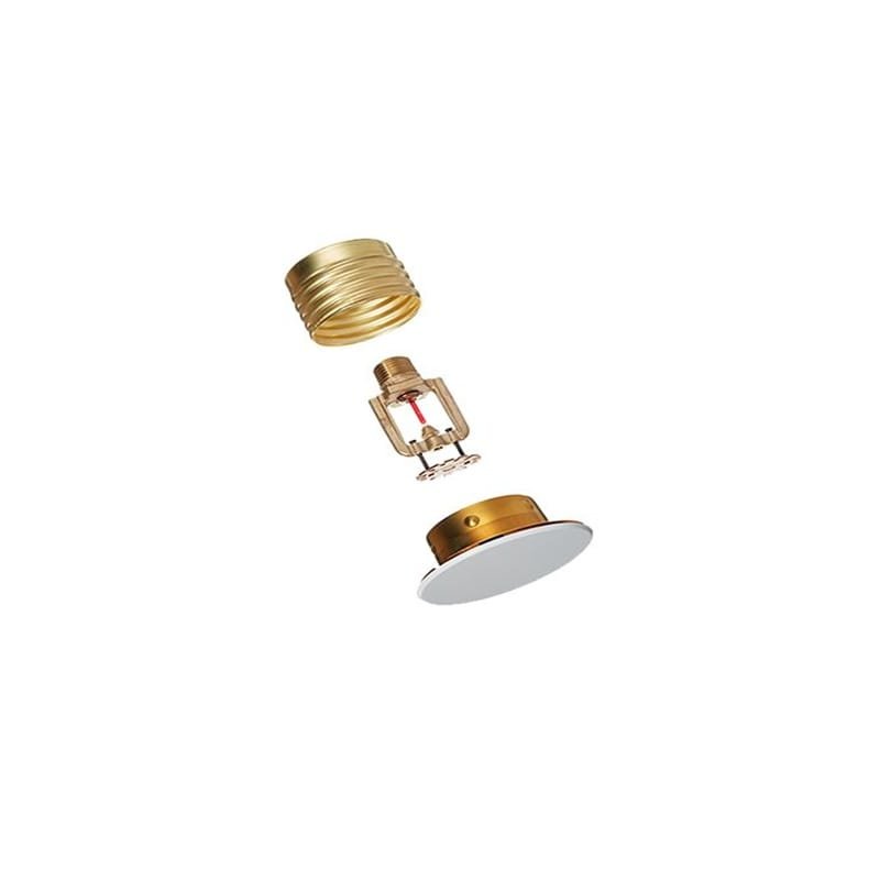
• Two-piece sprinkler/support-cup and cover-plate assembly.
MRI Environment Application:
The RFII-MRI sprinkler is designed for installation inside an MRI room, including areas close to the scanner unit.
According to the technical data sheet:
• It is acceptable under a static magnetic field of 7 Tesla or less.
• Standard MRI equipment is commonly in the 3-Tesla range.
• The sprinkler is installed at ceiling level and connected to fixed fire-protection piping.
• It must not be installed directly inside the MRI scanner.
• It must not be installed within the scanner bore.
Operation:
During normal conditions, the sprinkler is concealed above the ceiling by the cover plate.
When exposed to heat from a fire:
• The solder points holding the cover plate respond to heat.
• The cover plate releases and falls away.
• The deflector drops into its operating position.
• Fluid inside the glass bulb expands.
• The bulb breaks at its rated operating temperature.
• The sealing assembly releases.
• Water flows through the sprinkler orifice.
• The deflector distributes water across the designed coverage area.
Hydraulic Design Criteria:
16 ft × 16 ft Coverage:
• Approximate metric spacing: 4.9 m × 4.9 m.
• Minimum flow: 26 GPM.
• Metric flow: 98.4 LPM.
• Minimum pressure: 21.6 PSI.
• Metric pressure: 1.49 bar.
18 ft × 18 ft Coverage:
• Approximate metric spacing: 5.5 m × 5.5 m.
• Minimum flow: 33 GPM.
• Metric flow: 124.9 LPM.
• Minimum pressure: 34.7 PSI.
• Metric pressure: 2.39 bar.
20 ft × 20 ft Coverage:
• Approximate metric spacing: 6.1 m × 6.1 m.
• Minimum flow: 40 GPM.
• Metric flow: 151.4 LPM.
• Minimum pressure: 51 PSI.
• Metric pressure: 3.52 bar.
Discharge Coefficient:
• K-factor: 5.6 GPM/psi½.
• Metric K-factor: 80.6 LPM/bar½.
Maximum Working Pressure:
• 175 PSI.
• 12.1 bar.
Available Temperature Ratings:
Option 1:
• Sprinkler temperature: 155°F.
• Metric temperature: 68°C.
• Cover plate temperature: 139°F.
• Metric cover-plate temperature: 59°C.
Option 2:
• Sprinkler temperature: 200°F.
• Metric temperature: 93°C.
• Cover plate temperature: 165°F.
• Metric cover-plate temperature: 74°C.
Connection:
• 1/2-inch NPT.
Adjustment:
• 1/2 inch.
• 12.7 mm.
Main Construction Materials:
• Frame: Bronze.
• Support cup: Brass.
• Guide pins: Stainless steel.
• Deflector: Bronze.
• Compression screw: Brass.
• Bulb: Glass.
• Cap: Bronze or copper.
• Sealing assembly: Beryllium nickel with PTFE.
• Cover plate: Brass.
• Retainer: Brass.
• Ejection spring: Stainless steel.
Available Cover-Plate Finishes:
• Grey White – RAL 9002.
• Brass.
• Signal White – RAL 9003.
• Jet Black – RAL 9005.
• Custom factory finish.
Main Dimensions:
• Cover-plate diameter: 3.25 inches.
• Metric diameter: 82.6 mm.
• Cover-plate profile depth: 3/16 inch.
• Metric depth: 4.8 mm.
• Ceiling-clearance hole: 2.375 to 2.625 inches.
• Metric clearance hole: 60.3 to 66.7 mm.
• Sprinkler-fitting face to ceiling: 1.75 to 2.25 inches.
• Metric installation depth: 44.5 to 57.2 mm.
• Nominal air gap between cover plate and ceiling: 3/32 inch.
• Metric air gap: 2.4 mm.
Two-Piece Assembly Benefits:
• Allows sprinkler installation and system pressure testing before ceiling completion.
• Allows suspended-ceiling panels to be removed without removing the sprinkler.
• Provides vertical adjustment for sprinkler-drop coordination.
• Protects the sprinkler during ceiling work using the disposable cap.
• Allows the cover plate to be installed after ceiling completion.
Installation Requirements:
• Install only in the pendent orientation.
• The sprinkler centerline must be perpendicular to the ceiling.
• Use only the specified RFII sprinkler wrench.
• Required tightening torque is 7 to 14 lb-ft.
• Equivalent torque is 9.5 to 19 N·m.
• Do not compensate for incorrect elevation through over-tightening or under-tightening.
• Reposition the sprinkler fitting when required.
• Keep the protective cap installed during ceiling work.
• The system is considered out of service while the protective cap remains installed.
• Verify that the deflector moves freely before installing the cover plate.
• Do not install the cover plate in a manner that lifts a ceiling panel.
Care and Maintenance:
• Do not field paint the sprinkler or cover plate.
• Replace any sprinkler showing leakage or corrosion.
• Replace sprinklers damaged by impact, dropping or improper wrenching.
• Replace any sprinkler with a cracked bulb or loss of bulb liquid.
• Do not reinstall a removed sprinkler.
• Maintain the required air gap between the cover plate and ceiling.
• Do not allow ceiling paint to seal the air gap.
• Replace a dislodged cover plate immediately.
• Inspect, test and maintain the system in accordance with NFPA 25 and authority requirements.
Applications:
• MRI scanner rooms.
• Hospitals.
• Diagnostic imaging centers.
• Medical MRI facilities.
• Laboratories and magnetically sensitive areas.
• Light-hazard healthcare occupancies.
• Rooms requiring non-magnetic concealed sprinklers.
• Projects requiring extended coverage and a coordinated ceiling appearance.
Standards and Approvals Shown in the Data Sheet:
• UL Listed.
• C-UL Listed.
• ASTM F2052-15 for static magnetic-field testing.
• NFPA 13 for extended-coverage sprinkler-system design.
• NFPA 25 for inspection, testing and maintenance.
Important Note:
Suitability for an MRI room does not permit installation inside the scanner or scanner bore.
The final temperature rating, spacing, flow and pressure must be selected according to hydraulic calculations, MRI-room design, project specifications, NFPA requirements and the authority having jurisdiction.
Use only the listed RFII-MRI cover plate with a factory-applied finish. Do not modify or field paint the sprinkler or cover plate.
اطّلع على البيانات والمعلومات الفنية الكاملة للمنتج من خلال الكتالوج الرسمي.
Explore more products available in this category.