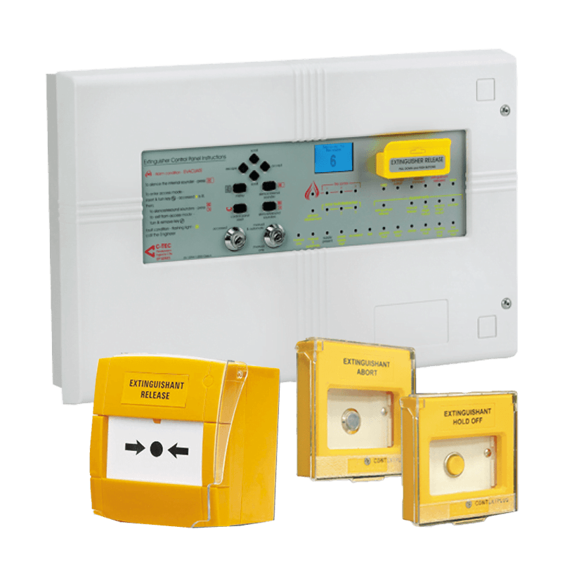
Context Plus EP203/CON Automatic Extinguisher Control Panel
Context Plus EP203/CON three-zone automatic extinguisher control panel for managing detection, staged alarms and gas-release sequences, with Hold, Abort, manual and automatic modes and LPCB certification.
العلامة التجارية
تفاصيل المنتج
نظرة عامة على المنتج
The Context Plus EP203/CON is a three-zone automatic extinguisher control panel designed to manage fire detection, staged alarms and the controlled release of gaseous or clean-agent fire suppression systems.
It combines the functions of a conventional three-zone fire alarm panel with dedicated extinguishing-release circuitry, monitored inputs, auxiliary outputs, manual and automatic operating modes, and remote-status capabilities.
Model:
• EP203/CON.
Product Type:
• Automatic Extinguisher Control Panel.
• Three-Zone Conventional Detection Panel.
• Gas-Release Control Panel.
Approvals and Standards:
The catalogue identifies compliance and certification to:
• LPCB.
• EN 12094-1 for fixed firefighting and gas-extinguishing control components.
• EN 54-2 for fire-alarm control and indicating equipment.
• EN 54-4 for power-supply equipment.
References shown include:
• LPCB Reference 176c.
• CE marking.
• 0832-CPD-0794.
The supplied product version and certificates must be matched to the project requirements.
Primary Functions:
• Receive signals from fire detectors.
• Monitor three conventional detection zones.
• Manage first- and second-stage alarms.
• Initiate the extinguishant-release sequence.
• Provide an adjustable pre-discharge delay.
• Support manual-only or manual-and-automatic operation.
• Monitor extinguishing-cylinder low pressure.
• Receive gas-flow or discharged signals.
• Operate warning devices.
• Control extract or ventilation functions.
• Send auxiliary signals to external systems.
• Record system events and faults.
Detection Zones:
The panel includes three conventional detection circuits.
Catalogue data includes:
• Three detection circuits.
• Circuit voltage from 21 to 28VDC.
• Open- and short-circuit monitoring.
• Maximum cable length of 250 meters per circuit.
• Up to 20 smoke or heat detectors per circuit.
• Up to 32 combined detectors and manual call points per circuit.
• Maximum zone quiescent current of 2mA.
• 6.8kΩ end-of-line resistor.
Circuit loading and cable arrangements must comply with the approved design and manufacturer instructions.
Release Sequence:
The panel can be programmed so that a selected combination of active detection zones initiates the extinguishing sequence.
A typical sequence may include:
1. Fire signal from the first detection zone.
2. First-stage alarm operation.
3. Confirmation from another programmed zone.
4. Second-stage alarm operation.
5. Start of the pre-discharge countdown.
6. Shutdown of ventilation and associated equipment.
7. Activation of the extinguishant-release output.
8. Receipt of the gas-flow or discharged signal.
9. Event recording and status display.
The required zone combination can be programmed according to the approved cause-and-effect matrix.
Graphic Display:
The panel includes:
• 128 × 64-pixel graphical display.
• Two-colour backlight.
• Clear system-status feedback.
• Menu-based programming.
• Fault, disablement and event display.
The display supports operation and commissioning without relying only on complex LED indications.
Operating Modes:
The panel supports:
• Manual Only.
• Manual and Automatic.
The operating mode is selected using front-panel keyswitch controls.
Manual-Only Mode:
Automatic extinguishant release from the detection zones is prevented, while manual release remains available according to the programming.
Manual-and-Automatic Mode:
The panel can automatically initiate the release sequence when the programmed detection conditions are satisfied.
Manual Release:
The front panel includes a protected yellow manual-release control.
External manual-release call points can also be connected for remote activation.
Manual release may be programmed as:
• Immediate.
• Delayed.
The selected operation must comply with the site fire strategy.
Hold Function:
The Hold input can suspend or delay the release sequence while the hold control is operated or according to the approved wiring logic.
This can provide additional time for verification or evacuation in selected applications.
Abort Function:
The Abort input can cancel the extinguishant-release sequence according to the selected wiring and programming logic.
Hold and Abort controls must be clearly identified and users must understand the difference between their functions.
Sounder Outputs:
The panel includes three conventional sounder circuits:
• Two first-stage circuits.
• One second-stage circuit.
Catalogue specifications include:
• 21 to 28VDC output.
• Each circuit fused at 200mA.
• Maximum cable length of 50 meters per circuit.
• Up to approximately ten 20mA polarized sounders per circuit.
• Open- and short-circuit monitoring.
Different audible or visual indications may be used to distinguish first-stage alarm from imminent release.
Extinguishant-Release Output:
The panel includes a dedicated output for operating the extinguishing solenoid or release device.
Catalogue data includes:
• 21 to 28VDC.
• Rated at 1A for up to five minutes.
• Adjustable release delay from 0 to 60 seconds.
• Adjustable firing duration from 1 to 300 seconds.
• Adjustable flooding time from 60 to 1,800 seconds.
• EP214 system line terminator for release-circuit monitoring.
Compatibility with the selected solenoid or actuator must be confirmed before connection.
Monitored Inputs:
Six monitored inputs are provided:
• Manual Release.
• Gas Flow Switch.
• Gas Low-Pressure Switch.
• Mode.
• Hold.
• Abort.
The inputs are monitored for normal, active, open-circuit and short-circuit conditions according to the specified resistance thresholds.
Auxiliary Outputs:
Six standard volt-free relay outputs are provided:
• Fire.
• Local Fire.
• Extract Fan.
• First Stage Active.
• Second Stage Active.
• Fault.
Relay-contact rating:
• 30VDC.
• 1A maximum.
An optional EP212 expansion relay board can provide additional outputs for:
• Reset.
• Mode.
• Discharged.
• Hold.
• Abort.
Remote Status Units:
Up to eight remote status units can be connected through the monitored RS485 bus.
Available options include:
• EP210F Flush-Mounted Remote Status Unit.
• EP210S Surface-Mounted Remote Status Unit.
• EP211 Economy Status Unit.
Depending on the selected unit, remote functions may include:
• Status LCD.
• Manual release.
• Manual/automatic mode switch.
• System-status indications.
This allows system monitoring and control from locations near the protected enclosure.
Power Supply:
Catalogue specifications include:
• 230VAC, 50/60Hz mains supply.
• Nominal 24VDC internal supply.
• Maximum 3A output.
• 1.5A continuous and 3A peak power rating.
• Two 12VDC 7Ah VRLA batteries connected in series.
• 0.7A battery charge current.
• Mains and battery-charger monitoring.
• Battery disconnection and failure monitoring.
• Earth-fault monitoring.
• Approximate 40mA quiescent drain during mains failure.
Required standby duration must be calculated using the actual connected load.
Status Indicators:
Panel indicators include:
• General Fire.
• Fire Zones.
• General Disablement.
• Zone Fault / Disable / Test.
• Hold.
• First Stage Output.
• Release Imminent.
• Extinguishant Released.
• Abort.
• Manual Only.
• Manual and Automatic.
• Supply Present.
• PSU Fault.
• General Fault.
• System Fault.
• Delays.
• Sounder Fault.
• Flooding Zone Fault.
• Low-Pressure Fault.
These indications provide immediate feedback during operation, testing and maintenance.
Event Log:
The panel includes a time-stamped event log for:
• Fire alarms.
• Faults.
• Disablements.
• Manual operations.
• Release events.
• Operating-mode changes.
• Reset events.
An alarm counter records the number of occasions the panel has entered an alarm condition.
Commissioning and Engineering Functions:
Available functions include:
• Zone-combination selection.
• Extinguishant-release delay setting.
• Firing-signal duration setting.
• Flooding-time setting.
• Extract-fan enable or disable.
• Extract operating-time adjustment.
• Sounder-delay adjustment.
• Remote-status-unit learning.
• Extinguishant-output termination selection.
• Operating-mode exception settings.
• Earth-fault monitoring control.
• Immediate or delayed manual release.
• Walk test.
• Relay-output testing.
• Sounder testing.
• Power-supply and battery-status display.
• Factory reset.
Compatible Ancillaries:
• EP212 Output Expansion Relay Board.
• EP210F Flush Remote Status Unit.
• EP210S Surface Remote Status Unit.
• EP211 Economy Status Unit.
• EP214 System Line Terminator.
• CP150ALB Abort Button.
• CP200HLB Hold Button.
• CP100RLR Yellow Release Call Point.
• EP215 IP66 Hold/Abort Button.
• BF372 Yellow Extinguishant Release Call Point.
• Bells.
• Sounder/Beacons.
• Xenon Beacons.
The final ancillary schedule depends on the system design and installation environment.
Applications:
• Server rooms.
• Data centers.
• Telecommunication rooms.
• Control rooms.
• Generator rooms.
• Electrical rooms.
• Archive-storage areas.
• Museums.
• Art galleries.
• Laboratories.
• Chemical facilities.
• Sensitive-equipment rooms.
• FM-200 fire suppression systems.
• Clean-agent extinguishing systems.
• Aerosol suppression systems where electrically compatible.
• Inert-gas extinguishing systems according to approved design.
Dimensions and Weight:
Approximate dimensions shown:
• Back box: 439 × 276 × 70mm.
• Front lid: 467 × 293 × 29mm.
• Approximate overall dimensions: 467 × 293 × 100mm.
Weight:
• Approximately 4.65kg without batteries.
Installation Notes:
• Install in a visible and accessible location.
• Provide a suitable dry indoor environment.
• Separate mains-power and signal cables.
• Follow manufacturer wiring diagrams.
• Use the correct end-of-line resistors.
• Label all zones and circuits.
• Keep the release device disconnected during initial testing.
• Use a safe dummy load to test the release circuit.
• Confirm sounder polarity.
• Provide correct earthing.
• Install batteries after wiring is complete.
• Protect the release circuit against accidental operation.
Testing and Commissioning:
Complete the following:
• Test every detection zone.
• Test open- and short-circuit faults.
• Test first-stage alarm.
• Test second-stage alarm.
• Test the release delay.
• Test manual release safely.
• Test Manual Only and Manual/Automatic modes.
• Test Hold.
• Test Abort.
• Test the release output using a safe test load.
• Test low-pressure input.
• Test gas-flow input.
• Test extract-fan operation.
• Test external system interfaces.
• Test remote status units.
• Review the event log.
• Train operators and maintenance personnel.
Maintenance:
• Inspect the panel and indicators.
• Review the event log.
• Test detection zones.
• Test warning devices.
• Test Hold and Abort controls.
• Test manual-release devices.
• Inspect and measure battery condition.
• Test mains-failure operation.
• Test the release circuit without operating the extinguishing system.
• Test pressure and flow inputs.
• Review the programmed delay.
• Confirm that the protected-area use has not changed.
• Record all inspection and maintenance activities.
Required Procurement Information:
• Extinguishing-agent type.
• Required detection-zone arrangement.
• Required cross-zone logic.
• Pre-discharge delay.
• Release solenoid or actuator type.
• Number of sounders and beacons.
• Required remote status units.
• Hold and Abort requirements.
• Relay-expansion requirement.
• BMS or fire-alarm interface requirements.
• Required standby duration.
• Required approvals.
• Consultant and authority requirements.
• Quantity.
Important Note:
The EP203/CON controls the extinguishing sequence but does not represent a complete fire suppression system by itself.
Detectors, release solenoid, warning devices, control buttons and all ancillaries must be selected to suit the extinguishing system and approved cause-and-effect design.
Programming, testing and commissioning must be completed by qualified personnel, with the physical release circuit isolated during tests that do not require actual agent discharge.
الوثائق الفنية
كتالوج المنتج
اطّلع على البيانات والمعلومات الفنية الكاملة للمنتج من خلال الكتالوج الرسمي.
Related Products
Explore More Products in the Same Category
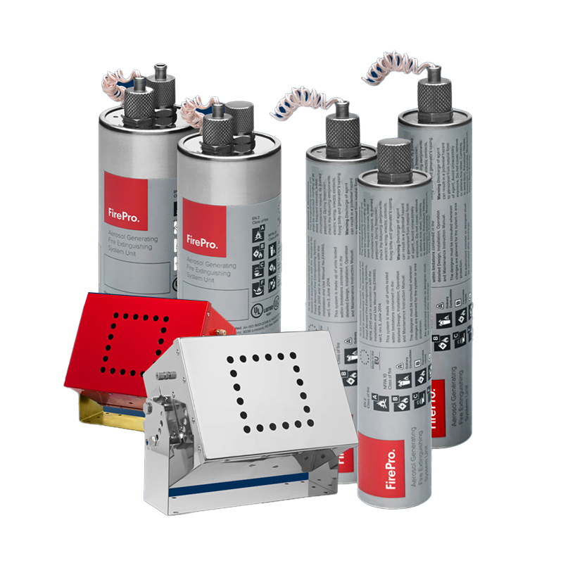
Gas fire suppression systems
FirePro Condensed Aerosol Fire Suppression System
Brand
FirePro
View Product
←

