Gas fire suppression systems
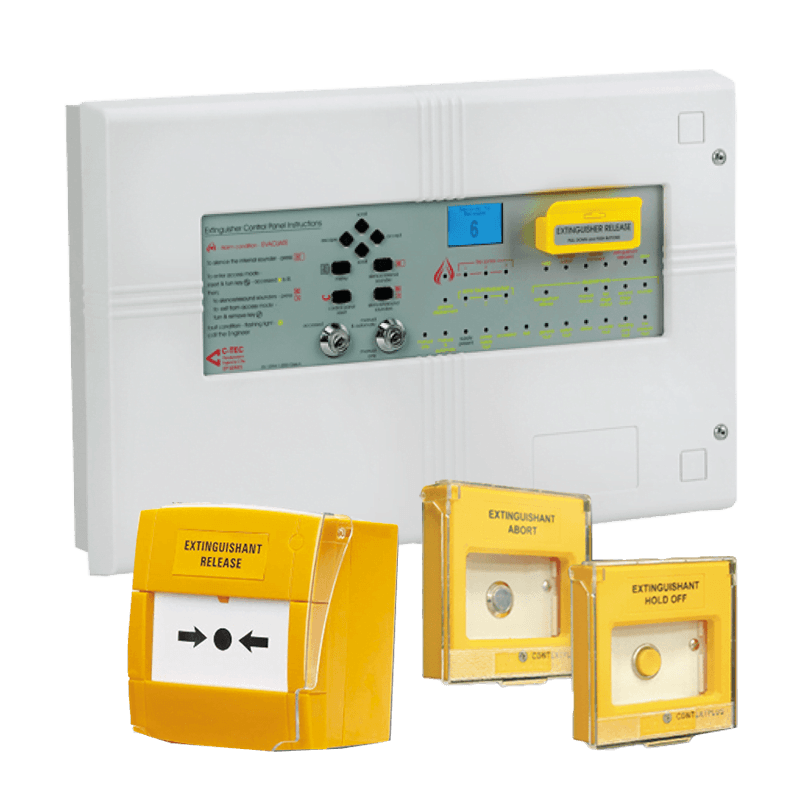
Context Plus EP203/CON Automatic Extinguisher Control Panel
Brand
Context Plus
View Product
←
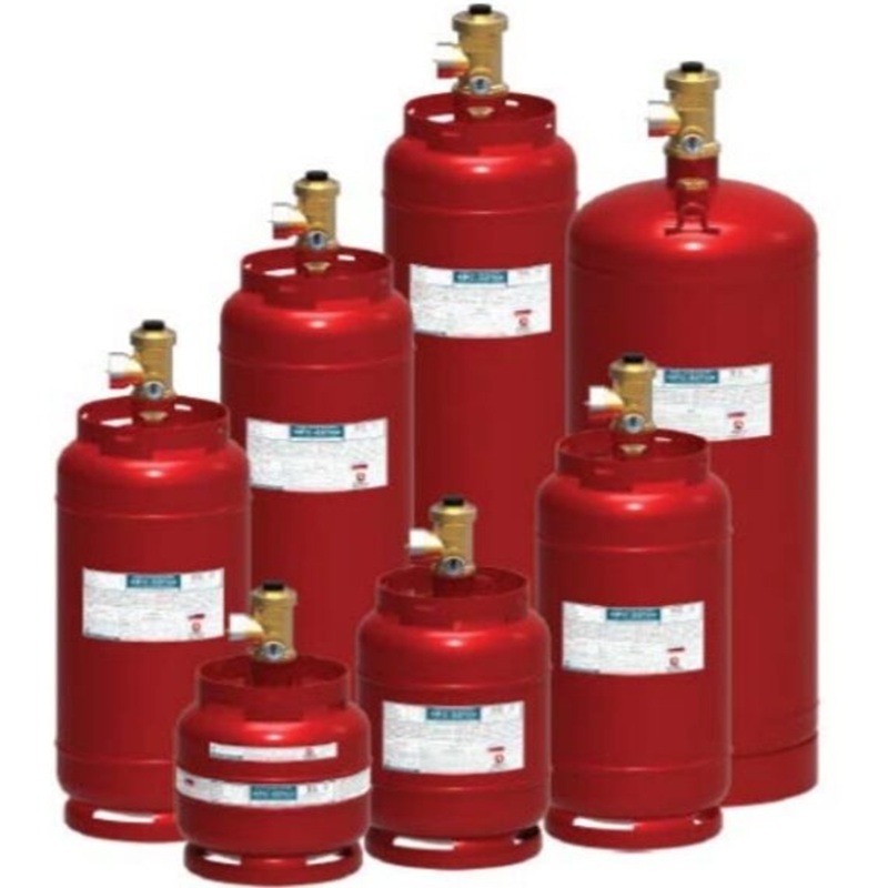
The American AFC FM-200 fire suppression system is a fixed clean-agent extinguishing solution using HFC-227ea to provide rapid protection for critical spaces, electrical equipment and valuable assets where water-based suppression may cause unacceptable damage.
The system stores liquid HFC-227ea in pressurized cylinders and releases it through an engineered piping and nozzle network after receiving an automatic or manual activation command.
The American AFC product family includes two primary system configurations:
• AFC-227.
• AFC-P227.
AFC-227 System:
The AFC-227 configuration uses HFC-227ea agent cylinders directly superpressurized with nitrogen.
It is suitable for applications where the piping arrangement, flow path and discharge requirements can be achieved using the standard cylinder pressure.
AFC-P227 System:
The AFC-P227 configuration uses a separate high-pressure nitrogen cylinder connected to the HFC-227ea agent cylinder.
The additional nitrogen provides increased propellant pressure for:
• Longer piping networks.
• More complex pipe arrangements.
• Multi-cylinder systems.
• Applications requiring additional pressure to achieve the specified discharge time.
Extinguishing Agent:
• HFC-227ea.
• Commonly known by the trade name FM-200.
• Waterless clean extinguishing agent.
• Suitable for many electrical and electronic hazards when used at the approved design concentration.
• Leaves no liquid residue after discharge.
• Helps reduce cleanup and business interruption.
Extinguishing Principle:
HFC-227ea primarily suppresses fire by absorbing heat and reducing the flame temperature below the level required to sustain combustion.
System performance depends on achieving the required design concentration within the specified discharge time and maintaining that concentration long enough to prevent re-ignition.
Main System Components:
• HFC-227ea agent-cylinder assemblies.
• Nitrogen-cylinder assemblies for AFC-P227.
• Cylinder discharge valves.
• Standard or 2n1 pressure gauges.
• Low-pressure supervisory switches.
• Agent flexible hoses.
• Nitrogen flexible hoses.
• Union elbows.
• Union-elbow adapters.
• Check valves.
• Manifold welding sockets.
• Distribution manifold.
• Electrical actuators.
• Pneumatic actuators.
• Manual actuators.
• Directional valves where required.
• Distribution piping.
• Discharge nozzles.
• Extinguishing control panel.
• Fire detectors.
• Audible and visual warning devices.
• Manual-release controls.
• Hold and Abort controls.
• Gas-flow or discharge switches.
• Cylinder mounting brackets.
AFC-227 Agent Cylinders:
The catalogue includes the following cylinder models:
• AFC-26.
• AFC-40.
• AFC-63.
• AFC-68.
• AFC-89.
• AFC-115.
• AFC-175.
The listed water capacities range from approximately:
• 26.8 liters.
• Up to 175 liters.
Agent fill ranges depend on cylinder capacity and the approved hydraulic calculation.
Smaller and medium cylinders use 40mm discharge valves, while selected larger cylinders use 50mm discharge valves.
AFC-P227 Agent Cylinders:
Available configurations include:
• AFC-P63.
• AFC-P68.
• AFC-P89.
• AFC-P115.
• AFC-P175.
Each model is connected to the appropriate nitrogen cylinder according to agent-cylinder size and required propellant pressure.
Nitrogen Cylinders:
The catalogue includes:
• ANC68-60.
• ANC68-70.
• ANC68-80.
Available fill pressures include:
• 60 bar.
• 70 bar.
• 80 bar.
The nitrogen cylinder provides additional pressure to drive HFC-227ea through longer or more complex piping networks.
Agent Fill Pressure:
HFC-227ea cylinders are filled at:
• 24.8 bar at 21°C.
• Approximately 360 PSI.
Cylinder Rated Working Pressure:
• 34.5 bar.
• Approximately 500 PSI.
Hydrostatic Test Pressure:
• 137.9 bar.
• Approximately 2,000 PSI.
Materials and Finish:
Agent cylinders:
• Carbon-steel construction.
• Red polyester powder-coated finish.
• Vertical installation.
Nitrogen cylinders:
• Seamless manganese-steel construction.
• Gray polyester powder-coated finish.
• Vertical installation.
Pressure Gauges:
Available options include:
• Standard pressure gauge.
• 2n1 pressure gauge.
Standard Gauge:
Displays the pressure inside the storage cylinder.
2n1 Gauge:
Combines:
• Pressure indication.
• Low-pressure electrical supervision.
The low-pressure contact can be connected to the extinguishing or fire-alarm control panel to provide a fault signal after a significant pressure drop.
Safety Devices:
Cylinder valves include pressure-relief and transport-safety provisions such as:
• Rupture disc.
• Safety plug.
• Safety caps.
These components protect against excessive pressure caused by high temperature and protect valve outlets during transport or when the cylinder is disconnected.
Flexible Hoses:
Flexible Hose 50A:
Transfers HFC-227ea from the agent cylinder to:
• The manifold.
• Or the distribution piping.
Catalogue data includes:
• Hydrostatic testing at 137.9 bar.
• EPDM and stainless-steel construction.
• Approximate overall length of 500mm.
Flexible Hose 20A:
Used in AFC-P227 systems to transfer pressurized nitrogen from the nitrogen cylinder to the HFC-227ea agent cylinder.
Different lengths are available to match cylinder combinations.
Manifold and Check Valve:
Multi-cylinder systems use a common distribution manifold.
The AFC-CV50 check valve is designed to:
• Prevent agent backflow.
• Prevent agent loss if a cylinder is removed.
• Protect personnel if the system operates while one cylinder is disconnected.
The valve, welding socket and manifold must be installed in accordance with the approved American AFC assembly details.
Activation Methods:
The system can be operated by:
• Electrical activation from the control panel.
• Pneumatic activation.
• Emergency manual activation.
• Sequential activation of multiple cylinders.
Electrical Actuator:
Receives the release signal from the control panel and operates the cylinder valve or release mechanism.
Pneumatic Actuator:
Uses pressure from the actuation line to open additional cylinders in multi-cylinder systems.
Manual Activation:
Provides emergency direct operation and must be protected against accidental activation.
Detection and Control:
The system is normally integrated with an extinguishing control panel to manage:
• Smoke and heat detection.
• Cross-zone logic.
• First-stage alarm.
• Second-stage alarm.
• Pre-discharge delay.
• Manual and automatic modes.
• Hold.
• Abort.
• Low-pressure supervision.
• Gas-flow or discharged indication.
• HVAC shutdown.
• Electrical-equipment shutdown.
• Audible and visual warning.
• Fire-alarm and BMS interfaces.
Applications:
FM-200 systems are commonly used to protect:
• Server rooms.
• Data centers.
• Telecommunication facilities.
• Control rooms.
• Electrical panels.
• Generator rooms.
• UPS rooms.
• Battery rooms subject to hazard assessment.
• Laboratories.
• Archives.
• Museums.
• Libraries.
• Medical equipment.
• Technical operating rooms.
• Petrochemical facilities.
• Marine engine rooms.
• Historical buildings.
• High-value assets.
Key Benefits:
• Rapid fire suppression.
• Waterless operation.
• No liquid residue.
• Suitable for electrical and electronic equipment.
• Reduced post-discharge cleanup.
• Suitable for occupied spaces at approved design concentrations.
• Wide range of cylinder capacities.
• Standard and nitrogen-driven configurations.
• Suitable for longer piping networks using AFC-P227.
• Pressure-supervision options.
• Integration with detection and control systems.
• Single- and multi-cylinder arrangements.
• UL Listed.
• FM Approved.
Approvals Shown:
• UL Listed.
• FM Approved.
• UL File Number EX29550.
• FM Approval PID PR472172.
• DOT cylinder approvals according to the listed cylinder type.
All supplied system components must be confirmed as part of the same approved system configuration.
Engineering Design:
The system must be designed using approved hydraulic-calculation software and manufacturer data.
Design activities include:
• Measuring protected enclosure dimensions.
• Calculating net volume.
• Identifying minimum and maximum temperature.
• Identifying the hazard.
• Calculating the design concentration.
• Calculating the required HFC-227ea quantity.
• Selecting cylinder quantity and capacity.
• Selecting AFC-227 or AFC-P227.
• Designing the piping network.
• Selecting pipe diameters.
• Determining nozzle quantity and location.
• Calculating nozzle flow and pressure.
• Confirming discharge time.
• Designing piping routes.
• Designing the manifold.
• Reviewing cylinder restraints.
• Preparing the cause-and-effect matrix.
• Selecting the detection and release logic.
• Calculating pressure-relief requirements where necessary.
• Conducting an enclosure-integrity test.
Room Integrity Testing:
The protected enclosure must retain the extinguishing concentration for the required holding time.
A door-fan test may be used to evaluate:
• Enclosure leakage.
• Concentration-holding time.
• Openings and penetrations.
• Required sealing work.
Changes to doors, walls, HVAC or service penetrations can affect system performance.
Pressure Relief:
Rapid clean-agent discharge may create a pressure change inside the enclosure.
The design must assess the need for:
• Pressure-relief venting.
• Required vent area.
• Venting direction.
• Protection of doors and walls.
• Coordination with mechanical and architectural work.
Occupied-Space Safety:
Use in occupied areas requires:
• Accurate concentration calculation.
• Compliance with exposure limits.
• Pre-discharge warning.
• Adequate evacuation delay.
• Hold and Abort controls where required.
• Clear operating instructions.
• Staff training.
• HVAC shutdown.
• Restricted re-entry after discharge until ventilation and inspection are complete.
Installation Notes:
• Install cylinders vertically.
• Use approved mounting brackets.
• Protect cylinders from impact.
• Provide service and replacement clearance.
• Keep pressure gauges visible.
• Use correct approved flexible hoses and fittings.
• Follow the specified tightening torque.
• Complete manifold welding using qualified personnel.
• Clean piping before installation.
• Prevent contamination inside the piping system.
• Secure piping against discharge forces.
• Install nozzles according to approved drawings.
• Protect actuators against accidental operation.
• Keep the final release actuator isolated until safe testing is complete.
Testing and Commissioning:
Before handover, complete:
• Cylinder and label inspection.
• Agent-fill-weight review.
• Cylinder-pressure inspection.
• Mounting-bracket inspection.
• Manifold and flexible-hose inspection.
• Piping tests according to the approved procedure.
• Electrical continuity testing.
• Low-pressure signal testing.
• Detector testing.
• First- and second-stage alarm testing.
• Release-delay testing.
• Hold and Abort testing.
• Safe manual-release testing.
• HVAC and equipment-shutdown testing.
• BMS and fire-alarm interface testing.
• Door-fan testing.
• Calculation and drawing review.
• Operator and maintenance training.
Maintenance:
• Inspect cylinder pressure.
• Verify agent weight when required.
• Inspect pressure gauges.
• Test low-pressure switches.
• Inspect cylinder valves.
• Inspect flexible hoses.
• Inspect manifolds and check valves.
• Test actuators.
• Inspect and test the control panel.
• Test detectors and warning devices.
• Test Hold and Abort controls.
• Inspect cylinder restraints.
• Check for corrosion.
• Review cylinder-test dates and service life.
• Repeat room-integrity testing after enclosure changes.
• Update hydraulic calculations after protected-space modifications.
After Discharge:
After system operation:
• Evacuate the protected area.
• Restrict entry until the area is declared safe.
• Ventilate the enclosure.
• Confirm fire extinction.
• Isolate discharged cylinders.
• Refill or replace agent cylinders.
• Inspect actuators, valves and hoses.
• Investigate the activation cause.
• Reset the control panel.
• Fully recommission the system.
• Update maintenance and discharge records.
Required Procurement Information:
• Protected enclosure dimensions.
• Net volume.
• Design temperature.
• Protected equipment and hazards.
• Number of protected zones.
• Piping length and routing.
• Nozzle quantity.
• AFC-227 or AFC-P227 configuration.
• Cylinder quantity and capacities.
• Pressure-gauge option.
• Single- or multi-cylinder system.
• Control-panel type.
• Release logic.
• Pre-discharge delay.
• Hold and Abort requirements.
• External-system interface requirements.
• Required approvals.
• Consultant and authority requirements.
Important Note:
An FM-200 system must not be selected only by cylinder size.
The required agent quantity, number of cylinders, pipe diameters, nozzle locations and selection between AFC-227 and AFC-P227 must be determined through approved hydraulic calculations.
All components must be compatible and included within the approved system listing, and the system must be designed, installed, tested and maintained by qualified specialists.
اطّلع على البيانات والمعلومات الفنية الكاملة للمنتج من خلال الكتالوج الرسمي.