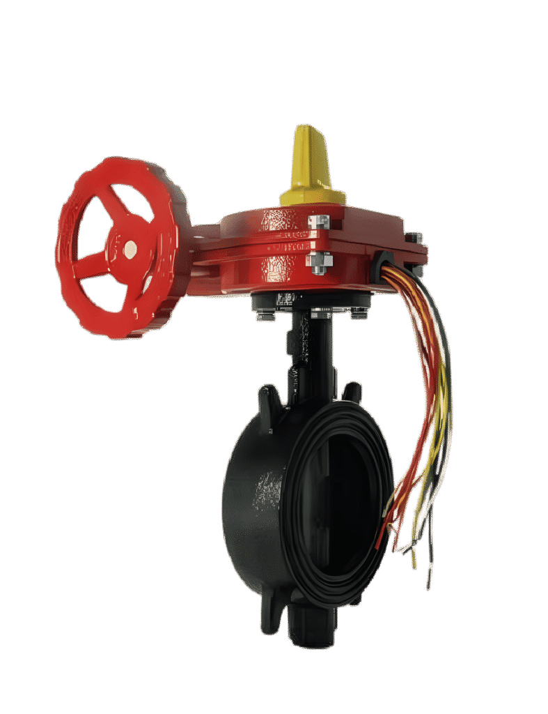
American AFC Wafer-Type Fire Butterfly Valve – BFW-300
American AFC BFW-300 wafer-type fire butterfly valve with a position indicator and built-in supervisory switch, available from 2 to 12 inches with a 300 PSI working pressure and UL/FM approvals.
العلامة التجارية
تفاصيل المنتج
نظرة عامة على المنتج
The American AFC BFW-300 Wafer-Type Fire Butterfly Valve is designed to control and isolate water flow within fire protection piping systems.
Its compact wafer-style body is installed between two pipe flanges without requiring integral flanged ends on the valve body.
The valve uses an internal disc that rotates through 90 degrees to control the waterway and is operated manually through a gearbox with a handwheel and clear position indicator.
Key Features:
• Fire protection butterfly valve.
• Model BFW-300.
• Wafer-type construction.
• Installed between piping flanges.
• Designed to MSS-SP-67 and API 609.
• Ductile iron disc fully encapsulated with EPDM.
• Bubble-tight shutoff.
• Flag-type open and closed position indicator.
• Low operating torque.
• High cycle life.
• Built-in supervisory switch.
• Suitable for connection to fire alarm and monitoring systems.
• Manual gearbox operation.
• Top operator mounting flange to ISO 5211/1.
• Compatible with ANSI B16.1 Class 125 flanges.
• Compatible with ANSI B16.5 Class 150 flanges.
• 300 PSI working pressure for sizes from 2 to 12 inches.
• Operating temperature from 0°C to 80°C.
• Suitable for indoor and outdoor use.
• Fusion-bonded epoxy coating to AWWA C550.
• UL Listed as shown in the catalogue.
• FM Approved as shown in the catalogue.
• Available in sizes from 2 to 12 inches.
Operation:
The valve is operated using a manual handwheel connected to a gearbox.
Rotating the handwheel causes the gearbox to rotate the internal disc through an angle of up to 90 degrees:
• When the disc is parallel to the water flow, the valve is open.
• When the disc is perpendicular to the water flow, the valve is closed.
The external indicator provides clear visual indication of valve position. The built-in supervisory switch can send a signal to the fire alarm control panel when the valve moves away from its fully open position.
Installation:
The valve body is positioned between two opposing pipe flanges and secured using the flange bolts.
The wafer-style construction helps reduce installation space and overall assembly weight compared with some fully flanged valve designs.
Flange Compatibility:
• ANSI B16.1 Class 125.
• ANSI B16.5 Class 150.
Available Sizes:
• 2 inches.
• 2.5 inches.
• 3 inches.
• 4 inches.
• 6 inches.
• 8 inches.
• 10 inches.
• 12 inches.
Valve Construction Materials:
• Valve body: Ductile Iron ASTM A536 65-45-12.
• Stem shaft: Stainless Steel 416.
• Disc: Ductile iron encapsulated with EPDM.
• Stem O-rings: EPDM.
• End-face seal: EPDM.
Gear Operator Materials:
• Gear housing: Ductile Iron ASTM A536 65-45-12.
• Gear cover: Cast Iron ASTM A126 Class B.
• Worm: Carbon Steel AISI 1045.
• Worm gear: Ductile Iron ASTM A536 65-45-12.
• Handwheel: Ductile Iron ASTM A536 65-45-12.
Maximum Torque at 300 PSI:
• 2 inches: 5 N·m.
• 2.5 inches: 5 N·m.
• 3 inches: 5 N·m.
• 4 inches: 6 N·m.
• 6 inches: 20 N·m.
• 8 inches: 21 N·m.
• 10 inches: 35 N·m.
• 12 inches: 40 N·m.
Supervisory Monitoring:
The valve includes a built-in supervisory switch that can be connected to a fire alarm system to monitor valve position.
This helps detect unauthorized or accidental movement of the valve from its fully open position toward a partially or fully closed position.
Applications:
• Automatic sprinkler systems.
• Fire hydrant systems.
• Fire hose networks.
• Fire pump rooms.
• Fire protection water-distribution lines.
• Fire network zone isolation.
• Indoor and outdoor fire protection systems.
• Flanged piping systems.
• Systems requiring valve-position monitoring from the fire alarm panel.
Standards and Approvals Shown in the Catalogue:
• UL Listed.
• FM Approved.
• MSS-SP-67.
• API 609.
• AWWA C550 for the protective coating.
• ISO 5211/1 for the operator mounting flange.
• ANSI B16.1 Class 125.
• ANSI B16.5 Class 150.
The appropriate valve size should be selected according to pipe diameter, flow rate, working pressure, flange type, hydraulic calculations and project requirements.
الوثائق الفنية
كتالوج المنتج
اطّلع على البيانات والمعلومات الفنية الكاملة للمنتج من خلال الكتالوج الرسمي.
Related Products
Explore More Products in the Same Category
Category Products
Fire Valves
Explore more products available in this category.
Fire Valves
American AFC Grooved Fire Butterfly Valve – BFG-300 and BFG-301
Brand
AFC
View Product
←