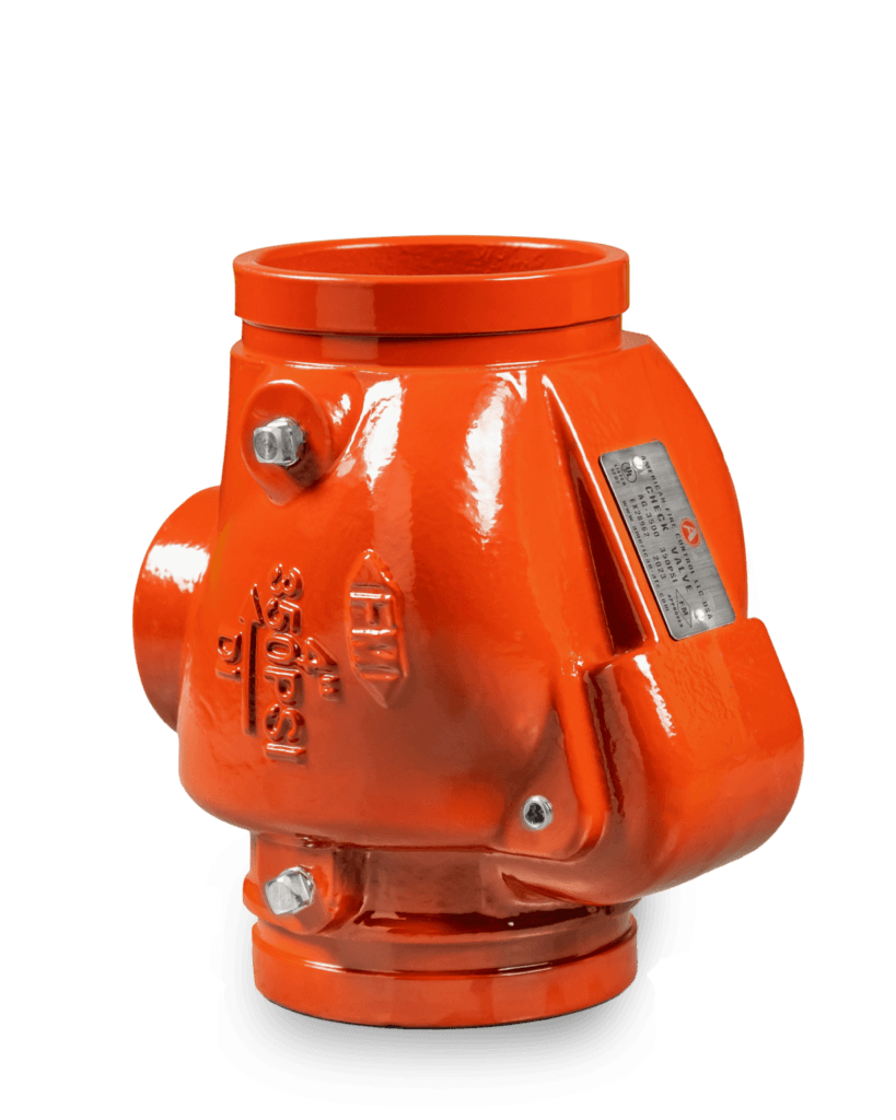
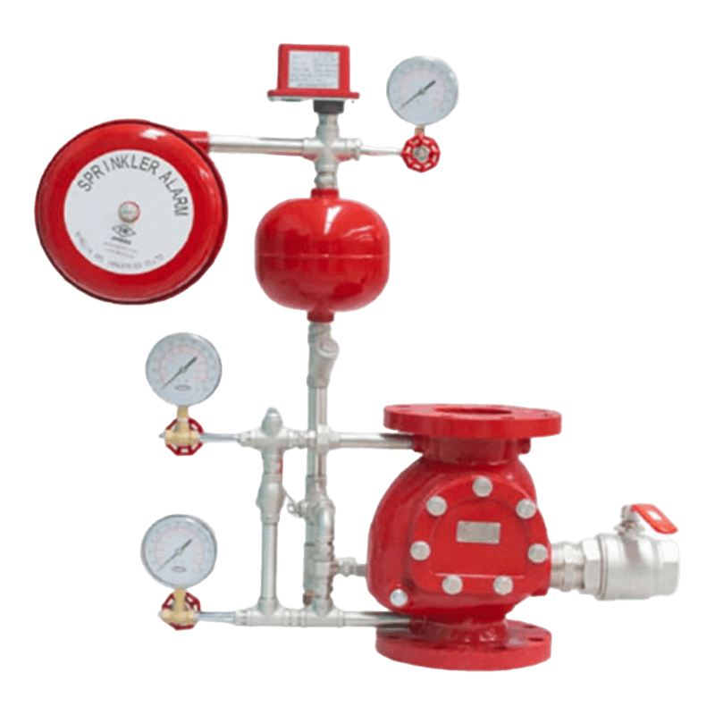
American AFC Wet Alarm Check Valve – ACV-300 Series
American AFC ACV-300 wet alarm check valve available with flanged, grooved or mixed connections, in sizes from 2 to 12 inches with a 300 PSI working pressure and UL/FM approvals.
العلامة التجارية
تفاصيل المنتج
نظرة عامة على المنتج
The American AFC ACV-300 Series Wet Alarm Check Valve is a primary component of wet-pipe automatic sprinkler systems.
It allows water to flow from the supply into the sprinkler network in one direction, prevents reverse flow toward the water supply and activates alarm devices when water flow occurs due to sprinkler operation.
This page combines all ACV-300 models because the catalogue presents them as one product family with the same basic design, components and operating principle. The main difference is the inlet and outlet connection arrangement.
Available Models:
• ACV-300F: Flanged ends.
• ACV-300G: Grooved ends.
• ACV-300FG: Flanged inlet and grooved outlet.
• ACV-300GF: Grooved inlet and flanged outlet.
Main Functions:
• Allows water flow from the supply into the sprinkler system.
• Prevents water from flowing back into the main supply.
• Detects water flow caused by sprinkler operation.
• Activates the water motor gong.
• Sends an electrical signal through the pressure switch.
• Reduces false alarms caused by pressure fluctuations.
• Supports fire-pump and auxiliary-equipment activation according to system design.
Key Features:
• Designed for wet-pipe sprinkler systems.
• ACV-300 model series.
• Available with flanged, grooved or mixed end connections.
• Vertical installation only.
• Maximum working pressure of 300 PSI or 21 bar.
• Operating temperature from 4°C to 70°C.
• Available in sizes from 2 to 12 inches.
• Ductile iron valve body.
• Internally and externally fusion-bonded epoxy coated.
• Equipped with a retard chamber.
• Equipped with a water motor gong.
• Equipped with a pressure switch.
• Equipped with pressure gauges.
• Equipped with a Y-strainer.
• Includes drain, test and control valves.
• UL Listed as shown in the catalogue.
• FM Approved as shown in the catalogue.
Operation:
Under normal standby conditions, the sprinkler piping is filled with pressurized water. The pressure on the system side is normally equal to or slightly higher than the pressure on the supply side.
The bypass line allows minor pressure surges to pass without lifting the valve clapper, helping prevent false alarms.
When a sprinkler opens due to a fire:
• Pressure drops on the system side.
• Differential pressure causes the alarm-valve clapper to open.
• Water flows from the supply into the sprinkler network.
• A portion of the water enters the alarm line and retard chamber.
• Water reaches the water motor gong and produces an audible alarm.
• The pressure switch converts water pressure into an electrical signal.
• The signal can be used to start the fire pump or transmit an alarm to the control panel.
Retard Chamber:
The retard chamber helps prevent false alarms caused by temporary water-supply pressure surges.
During a brief pressure surge, a limited quantity of water enters the chamber and is drained before reaching the alarm gong and pressure switch.
The operating manual indicates a delay time from 5 to 60 seconds and a chamber drainage time of less than 5 minutes.
Water Motor Gong:
The water motor gong operates using water flow and does not require electrical power.
Water rotates an internal turbine, causing the hammer to repeatedly strike the gong and produce a continuous mechanical alarm.
Pressure Switch:
The pressure switch converts alarm-line water pressure into an electrical signal.
It can be connected to a fire alarm control panel, fire-pump starting circuit or auxiliary fire protection equipment according to the project design.
End Connections:
ACV-300F:
• Flanged ends.
• ANSI B16.1 Class 125.
• ANSI B16.42 Class 150.
• BS EN 1092-2 PN16.
ACV-300G:
• Grooved ends.
• Groove dimensions comply with ANSI/AWWA C606.
Mixed Connection Models:
• ACV-300FG: Flanged to grooved.
• ACV-300GF: Grooved to flanged.
Available Sizes:
• 2 inches.
• 2.5 inches.
• 3 inches.
• 4 inches.
• 6 inches.
• 8 inches.
• 10 inches.
• 12 inches.
Main Components:
• Alarm check valve body.
• Valve clapper.
• Retard chamber.
• Water motor gong.
• Pressure switch.
• Pressure gauges.
• Y-strainer.
• Control and test ball valves.
• Bypass check valve.
• Trim piping and fittings.
• Main drain valve.
Main Construction Materials:
• Valve body: Ductile Iron ASTM A536 65-45-12.
• Selected trim components: Steel or Stainless Steel 304.
• Y-strainer: C954 or Stainless Steel 304.
• Ball valves and selected components: C954 or Stainless Steel 304.
• Pressure gauges and pressure switch: supplied components.
• Retard chamber: Steel.
• Alarm device: Water motor gong assembly.
Installation Requirements:
• Install the valve vertically.
• Locate the valve where it is visible and accessible.
• Confirm the water-flow direction arrow.
• Install all trim components according to the approved trim diagram.
• Properly support the retard chamber and connecting piping.
• Install the pressure switch vertically above the retard chamber.
• Provide adequate drainage for all drain outlets.
• Thoroughly flush the piping before placing the valve in service.
• Remove trapped air from the network to prevent intermittent or false alarms.
Testing and Commissioning:
• Test the sprinkler network for leakage.
• Gradually pressurize the system.
• Test the water motor gong.
• Test the pressure switch.
• Test the alarm line.
• Test the main drain.
• Verify stable water flow.
• Confirm that strainers and restriction orifices are unobstructed.
Periodic Maintenance:
• Clean the valve-clapper sealing surface.
• Inspect and replace worn rubber seals.
• Clean alarm-line restriction openings.
• Clean the Y-strainer.
• Clean the retard chamber.
• Test the water motor gong periodically.
• Test the pressure switch periodically.
• Check for leakage and blockage.
• Keep the alarm-line ball valve in the open position.
Applications:
• Hotels.
• Shopping malls.
• Hospitals.
• Theaters.
• Office buildings.
• Conference centers.
• Warehouses.
• High-rise buildings.
• Underground parking facilities.
• Commercial and industrial buildings using wet-pipe sprinkler systems.
Standards and Approvals Shown in the Catalogue:
• UL Listed.
• FM Approved.
• ANSI B16.1 Class 125.
• ANSI B16.42 Class 150.
• BS EN 1092-2 PN16.
• ANSI/AWWA C606 for grooved connections.
The final model, size and trim arrangement should be selected according to connection type, water pressure conditions, expected pressure fluctuations, sprinkler-system design and project requirements.
الوثائق الفنية
كتالوج المنتج
اطّلع على البيانات والمعلومات الفنية الكاملة للمنتج من خلال الكتالوج الرسمي.
Related Products
Explore More Products in the Same Category
Category Products
Fire Valves
Explore more products available in this category.
Fire Valves
American AFC Grooved Fire Butterfly Valve – BFG-300 and BFG-301
Brand
AFC
View Product
←