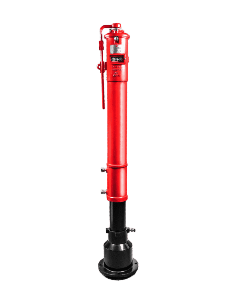
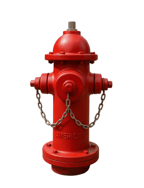
American AFC Dry Barrel Fire Hydrant – F-7700 and F-8700
American AFC dry barrel fire hydrant available as the F-7700 flanged-inlet model and F-8700 mechanical-joint model, with a 250 PSI operating pressure and UL/FM approvals.
العلامة التجارية
تفاصيل المنتج
نظرة عامة على المنتج
The American AFC F-7700 and F-8700 Dry Barrel Fire Hydrants provide an external connection point for firefighters to access water from an underground fire protection network.
The dry-barrel design places the main operating valve below ground level and drains the vertical barrel after the hydrant is closed. This prevents water from remaining inside the above-ground barrel and makes the hydrant suitable for locations where freezing temperatures may occur.
This product page combines two models from the same hydrant family because both use the same main design, appearance and technical characteristics. The primary difference is the inlet connection type:
• F-7700: Flanged inlet.
• F-8700: Mechanical-joint inlet.
Key Features:
• Dry-barrel fire hydrant.
• 6-inch DN150 main inlet.
• Available with a flanged or mechanical-joint inlet.
• Main steamer pumper connection.
• Two side fire-hose outlets.
• Maximum operating pressure of 250 PSI or 17.2 bar.
• 100% factory tested to 500 PSI or 34.5 bar.
• UL Listed as shown in the catalogue.
• FM Approved as shown in the catalogue.
• Conforms to AWWA C502 requirements.
• Ductile iron construction.
• Steel operating stem.
• Bronze seat and selected outlet components.
• Stainless Steel 304 below-ground fasteners.
• Internal and external red and black epoxy coating to AWWA C550.
• Suitable for outdoor fire protection and roadside service.
• Breakaway design allows traffic-damage repair without excavation.
• Seat and disc can be repaired without excavation.
• Low-torque seat and disc design for opening and closing.
• Multiple bury-depth options.
• Outlet caps supplied with retaining chains.
• Drain arrangement removes water from the barrel after closing.
Available Models:
F-7700:
The F-7700 is supplied with a 6-inch flanged inlet compatible with:
• ASME B16.5 Class 150.
• ISO PN16 flanged connection.
• DIN 2503 PN16 as shown in the data sheet.
F-8700:
The F-8700 is supplied with a 6-inch mechanical-joint inlet compatible with:
• AWWA Mechanical Joint.
• ANSI/AWWA C153 / A21.53 as shown in the technical sheet.
• The FM documentation includes the mechanical-inlet configuration within the approved dry-barrel hydrant models.
Hydrant Outlets:
The standard configuration shown in the catalogue includes:
• One 4.5-inch steamer pumper connection with 4NH thread.
• Two 2.5-inch hose outlets with 7.5NH thread.
Other outlet-thread types or selected pumper configurations may be available according to project requirements and the approved configuration.
Operation:
The hydrant is operated through the operating nut located on top of the bonnet.
When the hydrant is opened:
• The operating stem moves the main valve below ground.
• Water enters the hydrant from the underground fire network.
• The vertical barrel fills with water.
• Water becomes available through the side outlets and pumper connection.
When the hydrant is closed:
• The underground main valve closes.
• Water supply to the barrel stops.
• The lower drain port opens.
• Remaining water drains from the barrel to prevent standing water and freezing.
Traffic Breakaway System:
The design includes a breakaway connection near ground level.
When the above-ground portion is struck by a vehicle, the breakaway arrangement helps isolate the damage from the buried valve and underground components.
This allows selected traffic-damage repairs to be completed above ground without full excavation.
Main Construction Materials:
• Connector inlet: Ductile Iron ASTM A536 Grade 65-45-12.
• Lock nut: Ductile Iron ASTM A536 Grade 65-45-12.
• Connecting rod: Carbon Steel 1045 to ASTM A29/A29M.
• Gaskets and seals: EPDM to ASTM D2000.
• Lower barrel: Ductile Iron ASTM A536 Grade 65-45-12.
• Upper body: Ductile Iron ASTM A536 Grade 65-45-12.
• Outlet nipple and selected outlet components: C95400 Bronze to ASTM B148.
• Outlet caps: Ductile Iron ASTM A536 Grade 65-45-12.
• Selected bolts and fasteners: Carbon steel or Stainless Steel 304 according to component location.
• O-rings: NBR to ASTM D2000.
• Seat: C95400 Bronze to ASTM B148.
• Cushion: EPDM to ASTM D2000.
Available Bury Depths:
The catalogue shows approximate G dimensions including:
• 42 inches.
• 48 inches.
• 54 inches.
• 60 inches.
• 66 inches.
• 72 inches.
• 78 inches.
• 84 inches.
The appropriate bury depth should be selected according to underground pipe elevation, network depth, finished ground level and site conditions.
Applications:
• External fire hydrant networks.
• Industrial facilities.
• Warehouses and logistics areas.
• Manufacturing plants.
• Airports and ports.
• Residential and commercial developments.
• Roadside and outdoor fire protection.
• Locations exposed to freezing temperatures.
• Underground fire-water networks.
• Sites requiring an external water connection for firefighting operations.
Standards and Approvals Shown in the Catalogue:
• UL Listed.
• FM Approved.
• AWWA C502.
• AWWA C550 for the protective coating.
• ASME B16.5 Class 150 for the flanged inlet.
• ISO PN16.
• AWWA Mechanical Joint.
• ANSI/AWWA C153 / A21.53 for the shown mechanical-inlet configuration.
The final model, inlet type, bury depth and outlet threads should be selected according to project specifications, supply-pipe size, consultant requirements and the relevant authority.
الوثائق الفنية
كتالوج المنتج
اطّلع على البيانات والمعلومات الفنية الكاملة للمنتج من خلال الكتالوج الرسمي.
Related Products
Explore More Products in the Same Category
Category Products
Fire Valves
Explore more products available in this category.
Fire Valves
American AFC Grooved Fire Butterfly Valve – BFG-300 and BFG-301
Brand
AFC
View Product
←